Last Updated on October 22, 2020 by nghiaho12
A friend of mine from PunkOffice (punkoffice.com) recently hit me up and asked if I knew how to register a bunch of point clouds from his shiny Apply iPhone 11 that comes with a TrueDepth camera. He was interested in using it as a portable 3D scanner. Why yes I do! At least I did over a decade ago for my PhD. Back then I used the popular ICP (Iterative Closest Point) algorithm to do point-to-point registration. It did the job. But I wasn’t in the mood to reinvent the wheel again. So instead I searched for existing Python libraries that would get the job done with the least amount of effort. In my search I came across the Open3D library (http://open3d.org) that comes with Python bindings. This library includes file loaders for various 3D formats, a handful of registration methods, and a visualizer. Perfect!
What was meant to be a quick proof of concept eventually evolved into a mini R&D project as I sought for better registration accuracy!
The code is at the bottom of the page.
Problem we’re trying to solve
Essentially we’re trying to solve for the camera poses, that is its orientation and translation in 3D space. If we know the camera poses then creating a 3D point cloud from the individual captures is easy, we just project the 3D point out at that pose and we’re done. To do this we need to know the TruthDepth camera’s calibration and a dataset to work with.
Apple TrueDepth camera calibration
The first step was to gather any useful information about the TruthDepth camera. Apple has an API that allows you to query calibrationn data of the camera. I told my friend what I was looking for and he came back with the following
- raw 640×480 depth maps (16bit float)
- raw 640x480x3 RGB images (8bit)
- camera intrinsics for 12MP camera
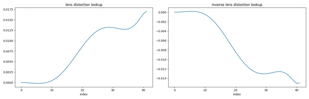
- lens distortion lookup (vector of 42 floats)
- inverse lens distortion lookup (vector of 42 floats)
Some intrinsic values
- image width: 4032
- image height: 3024
- fx: 2739.79 (focal)
- fy: 2739.79 (focal)
- cx: 2029.73 (center x)
- cy: 1512.20 (center y)
This is fantastic, because it means I don’t have to do a checkerboard calibration to learn the intrinsics. Everything we need is provided by the API. Sweet!
The camera intrinsics is for a 12MP image, but we’re given a 640×480 image. So what do we do? The 640×480 is simply a scaled version of the 12MP image, meaning we can scale down the intrinsics as well. The 12MP image aspect ratio is 4032/3204 = 1.3333, which is identical to 640/480 = 1.3333. The scaling factor is 640/4032 = 0.15873. So we can scale [fx, fy, cx, cy] by this value. This gives the effective intrinisc as
- image width: 640
- image height: 480
- fx: 434.89
- fy: 434.89
- cx: 322.18
- cy: 240.03
Now the distortion is interesting. This is not the usual radial distortion polynomial paramterization. Instead it’s a lookup table to determine how much scaling to apply to the radius. This is the first time I’ve come across this kind of expression for distortion. A plot of the distortion lookup is shown below
Here’s some pseudo code to convert an undistorted point to distorted point
def undistort_to_distort(x, y):
  xp = x - cx
  yp = y - cy
  radius = sqrt(xp*xp + yp*yp)
  normalized_radius = radius / max_radius

  idx = normalized_radius*len(inv_lens_distortion_lookup)
  scale = 1 + interpolate(inv_lens_distortion_lookup, idx)

  x_distorted = xp*scale + cx
  y_distorted = yp*scale + cy

  return x_distorted, y_distorted
idx will be a float and you should interpolate for the correct value, rather than round to the nearest integer. I used linear interpolation. To go from distorted to undistorted switch inv_lens_distortion_lookup with lens_distortion_lookup.
With a calibrated camera, we can project a 2D point to 3D as follows.
def project_to_3d(x, y, depth):
  xp = (x - xc)/fx * depth
  yp = (y - yc)/fy * depth
  zp = depth

  return [xp, yp, zp]
I found these links helpful when writing up this section.
- https://frost-lee.github.io/rgbd-iphone/
- https://developer.apple.com/documentation/avfoundation/avcameracalibrationdata
Dataset
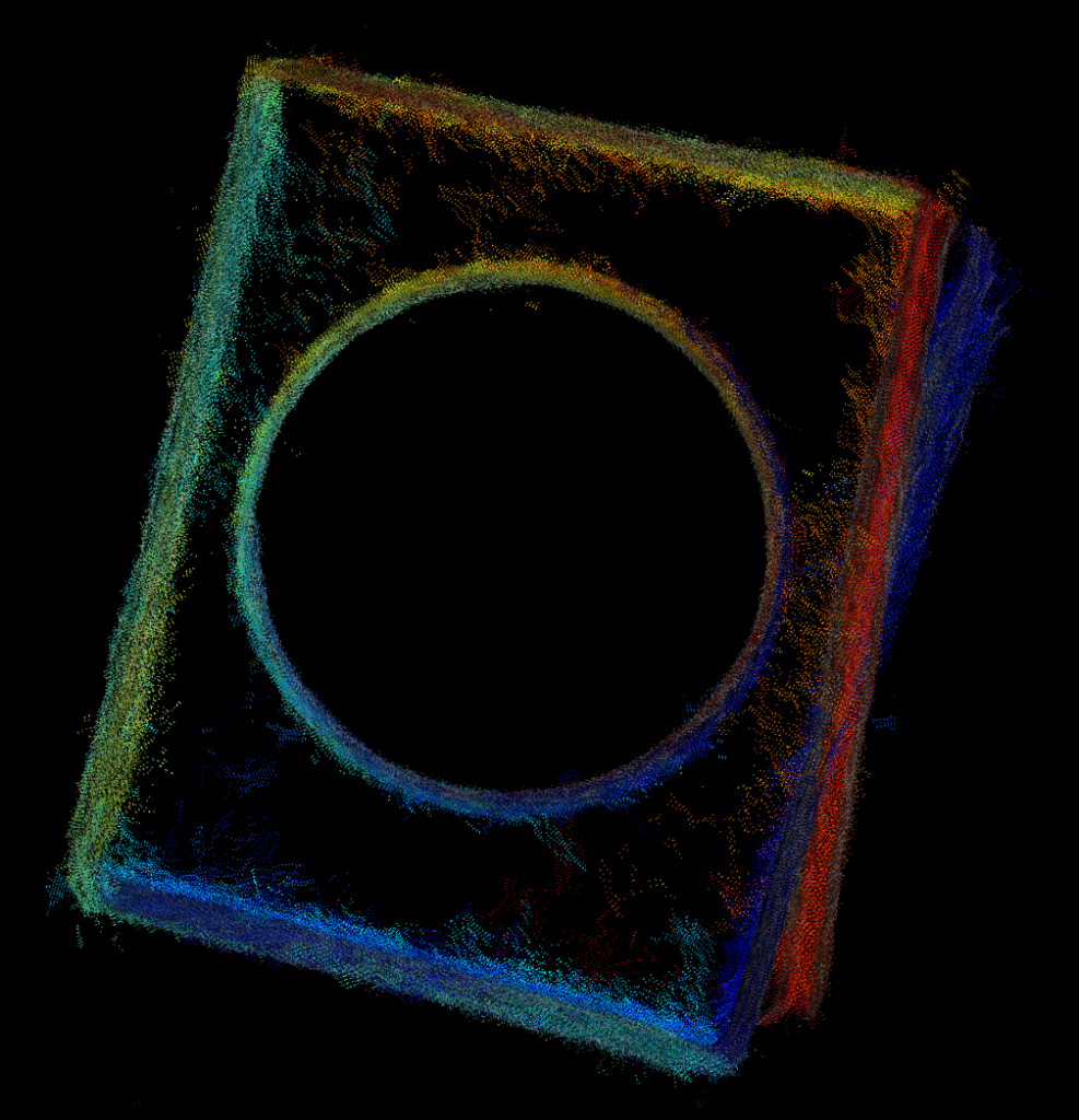
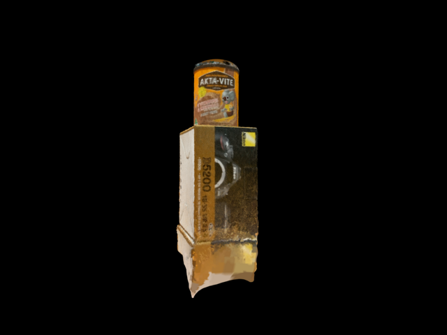
The dataset I got from my friend consists of 40 captures, which includes both RGB images and depth maps as shown below. I’m showing a gray image to save file space and I segmented the depth map to isolate the objects so you can see it better. There’s a box with a tin can on top, which are two simple shapes that will make it easy to compare results later on. The camera does a 360 or so degree pan around the object, which we’ll exploit later on as well.
Method #1 – Sequential ICP
The simplest method I could think of is sequential ICP. In this method the current point cloud is registered to the previous. I used Open3D’s point-to-plane variant of ICP, which claims better performance than point-to-point ICP. ICP requires you to provide an initial guess of the transform between the point clouds. Since I don’t have any extra information I used the identity matrix, basically assuming no movement between the captures, which of course isn’t true but it’s a good enough guess.
Below shows a top down view of the box and can. You can some misalignment of the box on the right side. This will be our baseline.
Method #2 – Sequential vision based
There are two drawbacks with the sequential ICP approach. First, using 3D points alone can not resolve geometric ambiguities. For example, if we were to capture a sequence of a flat wall, ICP would struggle to find the correct transform. Second, ICP needs an initial transform to boot strap the process.
To address these shortcomings ‘ll be using both the image and depth data. The image data is richer for tracking visual features. Here is an outline the approach
1. Track 2D SIFT features from current to previous frame
2. Use the fundmanmetal matrix to filter out bad matches
3. Project the remaining 2D points to 3D
4. Find the rigid transform between current and previous 3D points
We now have a good estimate for the transform between camera poses, rather than assume identity transform like with ICP!
The advantage estimating the transform in 3D is it’s much easier and possibly than traditional 2D approaches. The rigid transform can be calculated using a closed form solution. The traditional 2D approach requires calculating the essential matrix, estimating 3D points, solving PnP, … And for a monocular camera it’s even trickier!
Here’s the result of the sequential vision based approach
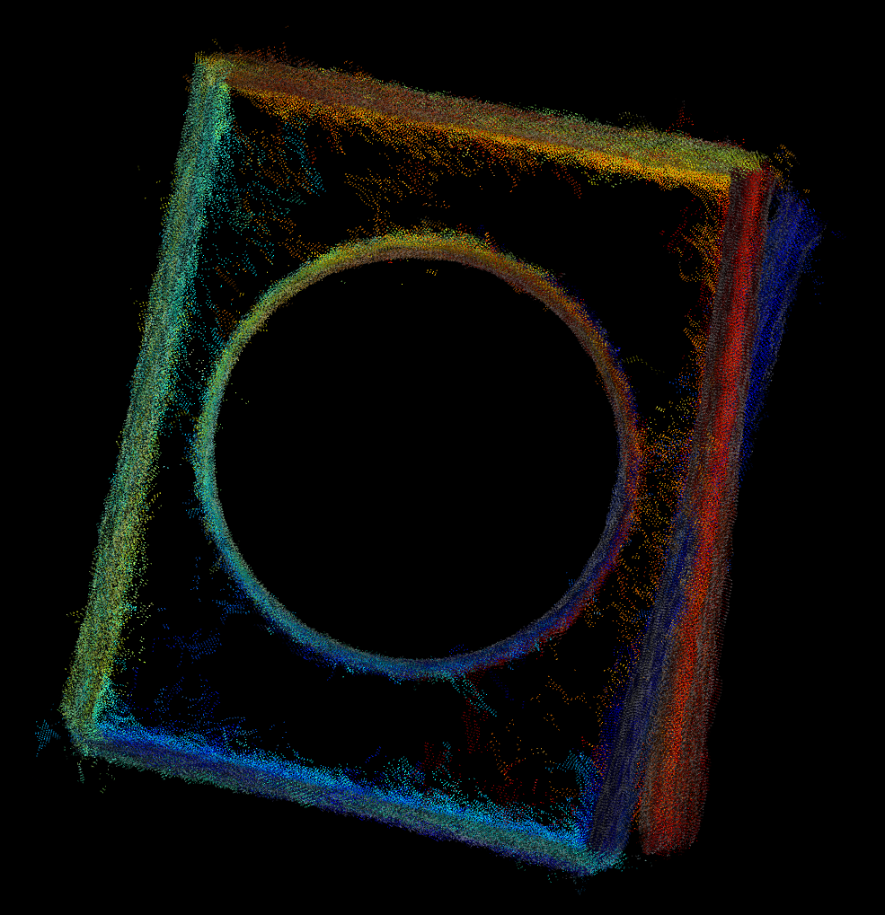
Hmm no noticeable improvement. Sad face. Still the same problem. Fundamentally, our simplistic approach of registering current to previous introduces a small amount of drift over each capture.
Oh fun fact, the SIFT patent expired some time early 2020! It got moved out of OpenCV’s non-free module and is now back in the features2d module.
Method #3 – Sequential vision based with loop closure detection
To reduce the effect of drift and improve registration we can exploit the knowledge that the last capture’s pose is similar to one of the earlier capture, as the camera loops back around the object. Once we find the loop closure match and the transform between them we can formulate this as a pose graph, plus feature matching constraints, and apply an optimization. Pose graph optimization is commonly used in the robotics community to solve for SLAM (simultaneous localization and mapping) type of problems. There are 3 main ingredients for this optimization
1. define the parameters to be optimized
2. define the cost function (constraint)
3. provide good initial estimates of the parameters
As mentioned earlier, we’re interested in solving for the camera poses (rotation, translation). These are the parameters we’re optimizing for. I chose to represent rotation as a Quaternion (4D vector) and translation as a 3D vector (xyz). So a total of 7 parameters for each camera. It’s also common to represent the rotation using an axis-angle parameterization, such that it’s a 3D vector. This will be faster to optimize but there are singularities you have to watch out for. See http://www.euclideanspace.com/maths/geometry/rotations/conversions/matrixToAngle for more insight. The Quaternion doesn’t have this problem, but requires the solver to make sure the vector is unit length to be a valid rotation vector.
For the cost function, given the current parameters, I want to minimize the Euclidean distance between the matching 3D points. Here’s a pseudo code for the cost function
def cost_func(rot1, trans1, rot2, trans2, pts1, pts2):
  # rot1, rot2 - quaternion
  # trans1, trans2 - 3D translation
  # pts1, pts2 - matching 3D point

  pts1_ = rotate_point(rot1, pts1) + trans1
  pts2_ = rotate_point(rot2, pts2) + trans2

  residuals[0] = pts1_.x - pts2_.x
  residuals[1] = pts1_.y - pts2_.y
  residuals[2] = pts1_.z - pts2_.z

  return residuals
We add a cost function for every 3D match. So this includes all the current to previous matches plus the loop closure match. The optimization algorithm will adjust the parameters iteratively to try and make the loss function approach zero. A typical loss function is loss = sum(residuals^2), this is the familiar least squares.
Pose graph optimization uses a non-linear optimization method, which requires the user to provide a good estimate of the parameters else it will converge to the wrong solution. We will use approach #2 to initialize our guess for the camera poses.
I used Ceres Solver to solve the pose graph. The results are shown below.
All the box edges line up, yay!
Method #4 – Sequential ICP with loop closure detection
Let’s revisit sequential ICP and see if we can add some pose graph optimization on top. Turns out Open3D has a built in pose graph optimizer with some sample code! Here’s what we get.
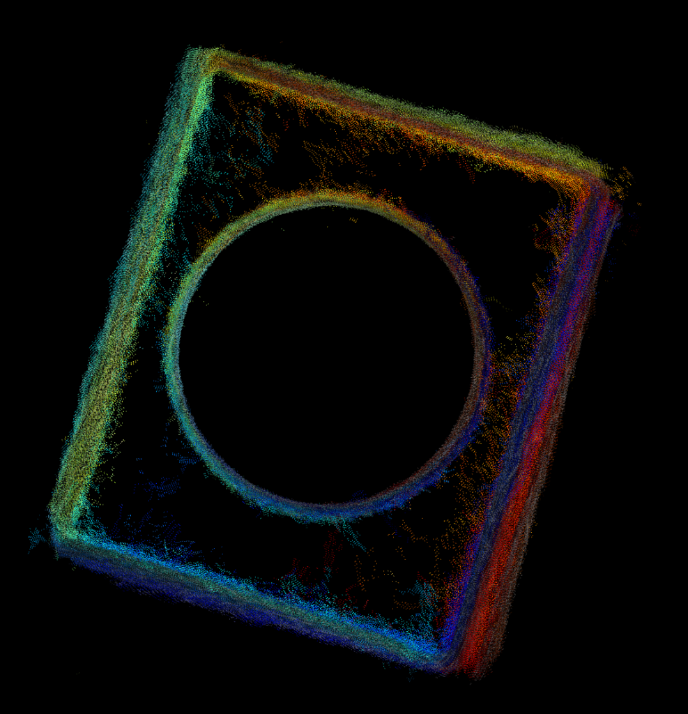
Better then vanilla sequential ICP, but not quite as good as the vision based method. Might just be my choice in parameters.
More improvements?
We’ve seen how adding loop closure to the optimization made a significant improvement in the registration accuracy. We can take this idea further and perform ALL possible matches between the captures. This can get pretty expensive as it scales quadratically with the number of images, but do-able. In theory, this should improve the registration further. But in practice you have to be very careful. The more cost functions/constraints we add the higher the chance of introducing an outlier (bad matches) into the optimization. Outliers are not handled by the simple least square loss function and can mess things up! One way to handle outliers is to use a different loss function that is more robust (eg. Huber or Tukey).
You can take the optimization further and optimize for the tracked 3D points and camera intrinsics as well. This is basically bundle adjustment found in the structure from motion and photogrammetry literature. But even with perfect pose your point cloud is still limited by the accuracy of the depth map.
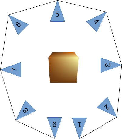
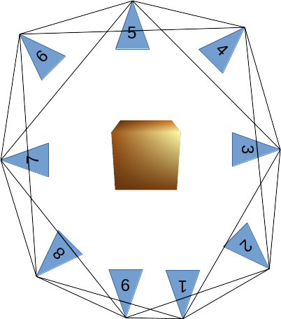
Summary of matching strategies
Here’s a graphical summary of the matching strategies mentioned so far. The camera poses are represented by the blue triangles and the object of interest is represented by the cube. The lines connecting the camera poses represents a valid match.
Sequential matching
Fast and simple but prone to drift the longer the sequence. Matching from capture to capture is pretty reliable if the motion is small between them. The vision based should be more reliable than ICP in practise as it doesn’t suffer from geometric ambiguities. The downside is the object needs to be fairly textured.
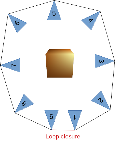
Vision based sequential matching with loop closure detection
An extension of sequential matching by explicitly detecting where the last capture loops back with an earlier capture. Effectively eliminates drift. It involves setting up a non-linear optimization problem. This can be expensive if you have a lot of parameters to optimize (lots of matched features). The loop closure detection strategy can be simple if you know how your data is collected. Just test the last capture with a handful of the earlier capture (like 10), and see which one has the most features matched. If your loop closure detection is incorrect (wrong matching pair of capture) then the optimization will fail to converge to the correct solution.
Finding all matches
This is a brute force method that works even if the captures are not ordered in any particular way. It’s the most expensive to perform out of the three matching strategies but can potentially produce the best result. Care must be taken to eliminate outliers. Although this applies to all method, it is more so here because there’s a greater chance of introducing them into the optimization.
Alternative approaches from Open3D
Open3D has a color based ICP algorithm (http://www.open3d.org/docs/release/tutorial/Advanced/colored_pointcloud_registration.html) that I have yet to try out but looks interesting.
There’s also a 3D feature based registration method that doesn’t require an initial transform for ICP but I haven’t had much luck with it.
http://www.open3d.org/docs/release/tutorial/Advanced/global_registration.html
Meshing
Open3D also includes some meshing functions that make it easy to turn the raw point cloud to a triangulated mesh. Here’s an example using Poisson surface reconstruction. I also filter out noise by only keeping the largest mesh, that being the box and tin can. Here it is below. It even interpolated the hollow top of the tin can. This isn’t how it is in real life but it looks kinda cool!
Final thoughts
Depending on your need and requirement you should always advantage of any knowledge of how the data was collected. I’ve shown a simple scenario where the user pans around an object. This allows for some simple and robust heuristics to be implemented. But if your aiming for something more generic, where there’s little restriction on the data collecting process, then you’re going to have to write more code to handle all these cases and make sure they’re robust.
This article is amazing!
It’s really easy to follow even for someone with zero experience in image processing like me.
Thank you for sharing.
Great article. The code on Github works great with the provided dataset.
I have however a query related to the dataset.
What was the format of the image and depth file? The downloaded dataset files are bin files. How did your friend generate the image and depth files? An insight into that would be great. Is there a code that they created to create these dataset files or iPhone has a feature to save these files in a specific format.
Thanks again.
The images are stored as raw RGB uint8 (no header), depth is raw float16. The image size had to be known in advance. Have a look at this post https://frost-lee.github.io/rgbd-iphone/.
Thanks for a quick reply. I will have a look at the article you shared.
A quick question – the code on the link you shared saves depth file as float32 file. According to their article, saving the data as float16 would be disparity values and not depths!
Also, would your code be able to read a normal jpg file (created using TrueDepth Camera) along with depth data file?
Thanks again.
Here’s more information https://developer.apple.com/documentation/avfoundation/avcapturephoto. I guess my friend must have saved out the depth map as float16.
It should be trivial to modify my code to read jpeg, at the moment it doesn’t.
Once again, I would like to ask a follow-on question. Will your code work if the camera is stationary and the object is placed on a rotating disk – e.g. if a cake is placed on a cake stand which can rotate. Will your code generate a 3D model using that image and depth data generated from this set of data?
Also, would it be possible for you to guide me in the direction of changing your code to read jpeg?
Thanks in advance.
Phil
If your cake has lots of visual features it should work and assuming it picks up minimal features from the background. Best to put a plain wall of some sort behind the cake.
Look at the function load_image in image_depth.py. Replace the np.fromfile with cv.imread.
Thanks. I will give it a go and get back to you.
Phil
One more follow up question – what changes I need to make to your code if I want to simply stitch various point clouds (as a monochrome 3D mega point cloud) from depth data files collected. Do I still need the image files or only depth data files will do the work?
Thanks for your continued help and apologies for a number of queries.
The object o3d.geometry.PointCloud() allows point cloud concatenation using the + operator.
Around the for loop that reads in image/depth data in process3d.py you can add it there.
Thanks a lot for a quick response, as always. Do I need the image files or I can ignore them to create a simple 3D point cloud which is stitched together.
Thanks again.
Phil
Images aren’t required.
I trust you are continuing to keep well in the midst of this pandemic.
I guess I am coming back to one of the fundamental questions – lensdistortionlookup and inverselensdistortionlookup are given by Apple as floating point values by default. However, the JSON file is looking for a string for these values. Would you please kindly clarify this aspect of getting these values for input to the program? The output at the moment seems quite jumbled up. I tried to convert the floating point values to characters but those characters appear to be very different from yours and they include multiple ” in the strings. In addition, one of the value in ILDL is zero and I can’t convert it to character so I am quite confused. The number of floating point values are identical to your values’ lengths.
Once again, thanks a lot for your help.
Did you try using my code to do the conversion?
Thanks again for your response. I have now managed to make it work by converting the floating point values to byte64.
I have a basic question – unfortunately I had to change my computer and the new one is a Mac. I have managed to compile the pose_graph (pose_graph.cpython-39-darwin.so is generated and is available in cpp and build folders. pose_graph.cpp file is also available in cpp folder. However, when I run the code, it gives the error – ModuleNotFoundError: No module named ‘pose_graph’. I have tried to recompile it multiple times but the same problem continues to happen. I have copied this file in every single possible folders but to no benefit. Previously I was on a Windows machine. I no longer have access to my that machine! I borrowed a friend’s windows machine and recompile it there but the same error is thrown on that machine too! Any idea of what’s wrong here?
Thanks.
What does your file listing for the cpp folder look like and how are you running the script?
0 drwxr-xr-x 7 224 2 Mar 21:40 .
0 drwxr-xr-x 16 512 3 Mar 11:28 ..
8 -rw-r–r– 1 425 2 Mar 17:18 CMakeLists.txt
0 drwxr-xr-x 9 288 2 Mar 21:40 build
32 -rw-r–r– 1 12903 2 Mar 17:18 pose_graph.cpp
7888 -rwxr-xr-x 1 4035256 2 Mar 21:40 pose_graph.cpython-39-darwin.so
0 drwxr-xr-x 22 704 2 Mar 17:43 pybind11
Folder structure of build is as follows:
0 drwxr-xr-x 9 288 2 Mar 21:40 .
0 drwxr-xr-x 7 224 2 Mar 21:40 ..
40 -rw-r–r– 1 20383 2 Mar 21:40 CMakeCache.txt
0 drwxr-xr-x 13 416 2 Mar 21:40 CMakeFiles
24 -rw-r–r– 1 8426 2 Mar 21:40 Makefile
8 -rw-r–r– 1 2580 2 Mar 21:40 cmake_install.cmake
8 -rw-r–r– 1 89 2 Mar 21:40 install_manifest.txt
7888 -rwxr-xr-x 1 4035256 2 Mar 21:40 pose_graph.cpython-39-darwin.so
0 drwxr-xr-x 5 160 2 Mar 21:40 pybind11
As far as compiling the pose_graph is concerned, I have followed your steps – including the ones given on ceres-solver website.
As far as your python script is concerned, I am using the command
python3 run.py images (I have changed a couple of default values of parameters. images is the folder where my images and depth files are stored.)
What does python3 –version return?
Python 3.7.6
Looks like you have multiple python versions. The default one doesn’t match the one used to compile pose graph. Try running the script with python3.9 run.py instead of python.
Thank you. This has worked after uninstalling python3.9.
I must confess, the code appears to work well in general. However, there is an issue – the model comes out with no specific front face. i.e. I would prefer to have the 3D model in a position where the first photo (or the last photo) taken provides the front view. Is there a way to control this in the 3D model?
Thanks again.
You’ll have to figure out the pose of the first camera and apply a reverse transform to the point cloud to make it an identity matrix.
Thanks for a quick response.
Do you mean – store the pose of the first camera at the time of transform [pc.pcd.transform(pc.pose)] and apply a reverse transform using this pose? I am able to locate 3 known points on the 3D model generated using either method 1 or 3. These 3 points give me a plane. I would like that plane to be directly in front of me. Any help would be greatly appreciated.
Thanks.
Yep, assuming that’s what I think you want. There might be some simpler function in Open3D where you can specify a position and a point to look at (haven’t look). OpenGL’s gluLookAt does this. Else you’ll have to derive your own transformation matrix.
Thanks once again. I have now created my own transformation matrix to achieve the desired result.
Hi Nghia,
I am trying to use your code using on own dataset captured from iPhone, but for some reason I keep getting the “Not enough matches!” error. I am not sure what I did wrong. I tried to changing max_vision_rsme but doesn’t seem to work This is my code for capturing the images:
let depth_base = CVPixelBufferGetBaseAddress(depth_buffer)!
let depth_bpr = CVPixelBufferGetBytesPerRow(depth_buffer)
let color_base = CVPixelBufferGetBaseAddress(color_buffer)!
let color_bpr = CVPixelBufferGetBytesPerRow(color_buffer)
var depth_array: Array = []
var color_array: Array = []
for y in 0..<buffer_height {
let depth_ptr = depth_base + (y*depth_bpr)
let depth_row = depth_ptr.assumingMemoryBound(to: Float16.self)
let color_ptr = color_base + (y*color_bpr)
let color_row = color_ptr.assumingMemoryBound(to: UInt8.self)
for x in 0..<buffer_width {
color_array.append(color_row[(x*4)+0])
color_array.append(color_row[(x*4)+1])
color_array.append(color_row[(x*4)+2])
color_array.append(color_row[(x*4)+3])
depth_array.append(depth_row[x])
}
}
// and then…
do {
print("saved depth"+String(n)+".bin")
let depth_data = Data(bytes: &depth_array, count: depth_array.count * MemoryLayout.stride)
try depth_data.write(to: path.appendingPathComponent(“depth”+String(n)+”.bin”), options: [])
} catch { print(“cannot write depth”) }
That error is from the args.min_matches parameter. The default is 30. Try lowering this.
thank you for the quick reply!
i tried various values for the min_matches parameters (even set it to 0), but the stitching algorithm now creates really weird results.
um… shouldn’t it be “lensDistortionLookupTable” instead of “inverseLensDistortionLookupTable”?
really appreciate your help.
i ended up using seq+closure. i don’t think i have enough features to use vision.
Hi Nghia
I have followed your steps on GitHub to install the code on Ubuntu 18.04 – it’s a Azure Data Science VM. I can successfully reach up to the stage of cmake in the build folder. However, make command results in an error as follows:
/home/Open3D/cpp/pose_graph.cpp:14:10: fatal error: ceres/ceres.h: No such file or directory
#include “ceres/ceres.h”
^~~~~~~~~~~~~~~
compilation terminated.
Any help would be appreciated.
Thanks
Is ceres installed on the VM?
sudo apt-get install libceres-dev
I installed ceres using above command. as you can see in my previous message, cmake finds it but make does not find it!!
output of CMake copy/pasted again…
— Found installed version of Eigen: /usr/lib/cmake/eigen3
— Found required Ceres dependency: Eigen version 3.3.4 in /usr/include/eigen3
— Found required Ceres dependency: glog
— Found installed version of gflags: /usr/lib/x86_64-linux-gnu/cmake/gflags
— Detected gflags version: 2.2.1
— Found required Ceres dependency: gflags
— Found Ceres version: 1.13.0 installed in: /usr with components: [LAPACK, SuiteSparse, SparseLinearAlgebraLibrary, CXSparse, SchurSpecializations, OpenMP]
— pybind11 v2.6.0
— Configuring done
— Generating done
— Build files have been written to: /home/Open3D/cpp/build
Find out where the header ceres.h is installed. The path might differ to the one I used.
Thanks. How do I find out where ceres.h is installed? ceres.h is found in /usr/include/ceres folder. If I change path of ceres.h to /usr/include/ceres/ceres.h in your cpp file, the error is then thrown at other ceres include files included in ceres.h.
What I fail to understand is: CMake is able to find ceres installation but make can’t find it!
Further to my previous message, I have realised that python and CXX are in anaconda environment on Azure VM. However, ceres and eigen do not appear to be in anaconda environment. my knowledge of conda is very limited. is there a way to point CXX to correct ceres include folder? Following is the output from CMake.
— The C compiler identification is GNU 7.5.0
— The CXX compiler identification is GNU 7.5.0
— Check for working C compiler: /anaconda/envs/py38_default/bin/x86_64-conda-linux-gnu-cc
— Check for working C compiler: /anaconda/envs/py38_default/bin/x86_64-conda-linux-gnu-cc — works
— Detecting C compiler ABI info
— Detecting C compiler ABI info – done
— Detecting C compile features
— Detecting C compile features – done
— Check for working CXX compiler: /anaconda/envs/py38_default/bin/x86_64-conda-linux-gnu-c++
— Check for working CXX compiler: /anaconda/envs/py38_default/bin/x86_64-conda-linux-gnu-c++ — works
— Detecting CXX compiler ABI info
— Detecting CXX compiler ABI info – done
— Detecting CXX compile features
— Detecting CXX compile features – done
— Found installed version of Eigen: /usr/lib/cmake/eigen3
— Found required Ceres dependency: Eigen version 3.3.4 in /usr/include/eigen3
— Found required Ceres dependency: glog
— Found installed version of gflags: /usr/lib/x86_64-linux-gnu/cmake/gflags
— Detected gflags version: 2.2.1
— Found required Ceres dependency: gflags
— Found Ceres version: 1.13.0 installed in: /usr with components: [LAPACK, SuiteSparse, SparseLinearAlgebraLibrary, CXSparse, SchurSpecializations, OpenMP]
— pybind11 v2.6.0
— Found PythonInterp: /anaconda/envs/py38_default/bin/python (found version “3.8.12”)
— Found PythonLibs: /anaconda/envs/py38_default/lib/libpython3.8.so
— Performing Test HAS_FLTO
— Performing Test HAS_FLTO – Success
— Configuring done
— Generating done
Please ignore my previous messages. I have now found the way to install it in Conda environment.
Just used the following:
conda install -c conda-forge ceres-solver
Thanks and apologies for any confusion/inconvenience caused.
Further to my previous message, CMakeCache.text in the build folder has following:
//The directory containing a CMake configuration file for Ceres.
Ceres_DIR:PATH=/usr/lib/cmake/Ceres
cmake ../ command generates the following output.
— Found installed version of Eigen: /usr/lib/cmake/eigen3
— Found required Ceres dependency: Eigen version 3.3.4 in /usr/include/eigen3
— Found required Ceres dependency: glog
— Found installed version of gflags: /usr/lib/x86_64-linux-gnu/cmake/gflags
— Detected gflags version: 2.2.1
— Found required Ceres dependency: gflags
— Found Ceres version: 1.13.0 installed in: /usr with components: [LAPACK, SuiteSparse, SparseLinearAlgebraLibrary, CXSparse, SchurSpecializations, OpenMP]
— pybind11 v2.6.0
— Configuring done
— Generating done
— Build files have been written to: /home/Open3D/cpp/build
Traceback (most recent call last):
File “run.py”, line 2, in
from lib.process3d import process3d
File “../../Open3D_TrueDepth_registration/lib/process3d.py”, line 14, in
from cpp.pose_graph import optimize_pose_graph_with_matches, optimize_pose_graph_with_odometry
ModuleNotFoundError: No module named ‘cpp.pose_graph’
I followed the description as your guideline but, there’s some issue as above.
I tried to implement the code on Mac. Is this problem?
I’ve seen this happen when there are multiple python versions installed. Is this your situation?
Thank to your feedback, I solved them.
And how to save RGB-D images to .bin file format?
Thank to you, I solve the issue.
But, how to save the point cloud to bin file format?
I have the same problem, can you tell me your solution
Thank to your answer, I solved the issue.
And I have a question about how to save the depth, rgb into bin file.
Or, without using bin file, is it possible to register with png files?
Is it possible to register with RGB-D as png or jepg not bin file format?
Thanks to your answer, I solved the issue that not to be able to build.
And also, is it possible to register with png file format not bin file format?
You’ll have to modify the Python script.
Thank you for the code and tutorial!
I have a question regarding whether or not the depth data should be saved as a .json file?
I’ve been using this sample code https://frost-lee.github.io/rgbd-iphone/ to capture the TrueDepth data. The depth data is saved as a .json file and when I try to run your code I get a value error: cannot reshape array of size 5869091 into shape (480,640,4).
My code expects the depth as a binary dump, not json.
Hi, thanks for this tutorial. I’m trying to build multi-view SFM from scratch. Can you please explain how your friend got the camera intrinsics and lens distortion parameters from their iphone? I want the intrinsics from my iphone 12 but cannot seem to find a tutorial on the same. I was wondering if its possible to get this information without using the checkboard calibration.
Try https://frost-lee.github.io/rgbd-iphone/
Hi Nghia,
Thank you for all these useful learning contents and materials.
I have a code that uses an iPhone TrueDepth camera for reconstruction. It was working well on iPhone 12 but reconstruction for 13 and 14 are noisy.
Apparently, the sensors are changed. I also read somewhere else that there is some issue with the intrinsic parameters that Apple provides.
Do you have any insights on this? Have you tried iPhone 14 for reconstruction?
I haven’t worked on this project for a long time so don’t have any insights.
Hi thanks for writing this article.
I am also trying calibrate the TrueDepth camera without the OpenCV checkerboard calibration however the iPhone X was calibrated with a reference resolution of 3088×2320. So would scaling the intrinsics to 640×480 be as simple as multiplying fx, cx by (640/3088) and fy, cy by (480/2320) since they are clearly different aspect ratios.
Thanks.
Try scaling fx, fy, cx, cy by the same value. 3088×2320 has very similar aspect ratio to 640×480 that it might work.