Last Updated on April 4, 2017 by nghiaho12
With some more free time lately I’ve decided to get back into some structure from motion (SFM). In this post I show a simple SFM pipeline using a mix of OpenCV, GTSAM and PMVS to create accurate and dense 3D point clouds.
This code only serves as an example. There is minimal error checking and will probably bomb out on large datasets!
Code
https://github.com/nghiaho12/SFM_example
You will need to edit src/main.cpp to point to your dataset or you test with my desk dataset.
https://nghiaho.com/uploads/desk.zip
Introduction
There are four main steps in the SFM pipeline code that I will briefly cover
If your code editor supports code folding you can turn it on and see each step locally scoped around curly braces in src/main.cpp.
To simplify the code I assume the images are taken sequentially, that is each subsequent image is physically close and from the same camera with fixed zoom.
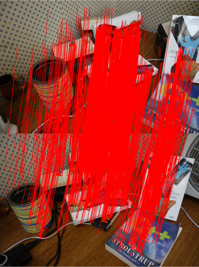
Feature matching
The first step is to find matching features between the images. There are many OpenCV tutorial on feature matching out there so I won’t go into too much detail.
There are a few ways to go about picking pair of images to match. In my code I match every image to each other. So if there N images, there are N*(N-1)/2 image pairs to match. This of course can get pretty slow since it scales quadratically with the number of images.
I initially tried ORB but found AKAZE to produce more matches. Matches have to past a ratio test (best match vs second best match) and the fundamental matrix constraint to be kept.
The only slightly tedious part is the book keeping of matched features. You need to keep track of features that match across many images. For example, a feature in image 0 may have a match in image 1 and image2. This is important because features that are seen in at least 3 views allow us to recover relative scale between motion.
Motion recovery and triangulation
This is the core part of the SFM pipeline and I take advantage of the following OpenCV functions
- cv::findEssentialMat
- cv::recoverPose
- cv::triangulatePoints
cv::findEssentialMat uses the 5-point algorithm to calculate the essential matrix from the matched features. It’s the de-facto algorithm for finding the essential matrix and is superior to the 8-point algorithm when used in conjunction with RANSAC to filter out outliers. But it is not easy to code up from scratch compared to the 8-point.
The pose from the essential matrix is recovered by cv::recoverPose. It returns a 3×3 rotation (R) and translation vector (t). The pose at camera n is calculated as follows
![T_n = T_{n-1}\left[\begin{array}{ccc|c} & & \\ & R & & t\\ & & \\ 0 & 0 & 0 & 1 \end{array}\right]](https://s0.wp.com/latex.php?latex=T_n+%3D+T_%7Bn-1%7D%5Cleft%5B%5Cbegin%7Barray%7D%7Bccc%7Cc%7D+%26+%26+%5C%5C+%26+R+%26+%26+t%5C%5C+%26+%26+%5C%5C+0+%26+0+%26+0+%26+1+%5Cend%7Barray%7D%5Cright%5D&bg=ffffff&fg=000000&s=0 "T_n = T_{n-1}\left[\begin{array}{ccc|c} & & \\ & R & & t\\ & & \\ 0 & 0 & 0 & 1 \end{array}\right]")
 is a 4×4 matrix.
Given two poses the 2D image points can then be triangulated using cv::triangulatePoints. This function expects two projection matrices (3×4) as input. To make a projection matrix from the pose you also need the camera matrix K (3×3). Let’s say we break up the pose matrix 

![T_n = \left[\begin{array}{ccc|c} & & \\ & R_n & & t_n\\ & & \\ 0 & 0 & 0 & 1 \end{array}\right]](https://s0.wp.com/latex.php?latex=T_n+%3D+%5Cleft%5B%5Cbegin%7Barray%7D%7Bccc%7Cc%7D+%26+%26+%5C%5C+%26+R_n+%26+%26+t_n%5C%5C+%26+%26+%5C%5C+0+%26+0+%26+0+%26+1+%5Cend%7Barray%7D%5Cright%5D&bg=ffffff&fg=000000&s=0 "T_n = \left[\begin{array}{ccc|c} & & \\ & R_n & & t_n\\ & & \\ 0 & 0 & 0 & 1 \end{array}\right]")
The 3×4 projection matrix for the camera n is
![P_n = K\left[\begin{array}{c|c} R_n^T & -R_n^{T}t_n\end{array}\right]](https://s0.wp.com/latex.php?latex=P_n+%3D+K%5Cleft%5B%5Cbegin%7Barray%7D%7Bc%7Cc%7D+R_n%5ET+%26+-R_n%5E%7BT%7Dt_n%5Cend%7Barray%7D%5Cright%5D&bg=ffffff&fg=000000&s=0 "P_n = K\left[\begin{array}{c|c} R_n^T & -R_n^{T}t_n\end{array}\right]")
This process is performed sequentially eg. image 0 to image 1, image 1 to image 2.
There is an ambiguity in the scale recovered from the essential matrix (hence only 5 degrees of freedom). We don’t know the length of the translation between each image, just the direction. But that’s okay, we can use the first image pair (image 0 and image 1) and use that as the reference for relative scale. An illustration of how this is done is shown below. Click on the image to zoom in.
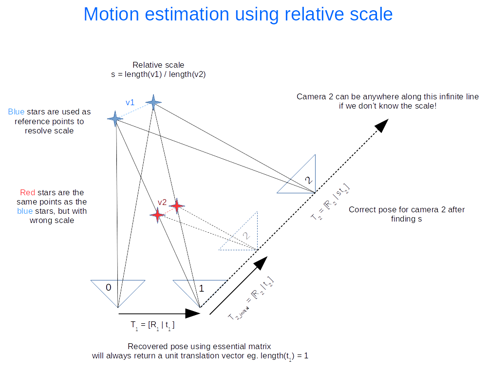
The following calculations occurs
- Recover motion between image 0 and 1 and triangulate to get the blue points. These points will be used as the reference to figure out the relative scale.
- Recover motion between image 1 and image 2 and triangulate to get the red points. Using our 2D feature matching done earlier we find that they are the same as the blue points. The rotation (
) is correct, but the translation (
) needs to be scaled.
- Find the relative scale by picking a pair of blue points and the matching red points and calculate the ratio of the vector lengths.
- Apply the scale to
Everything I’ve outlined so far is the basically visual odometry. This method only works if the images are taken sequentially apart.
Bundle adjustment
Everything we’ve done so far more or less works but is not optimal, in the statistical sense. We have not taken advantage of constraints imposed by features matched across multiple views nor have we considered uncertainty in the measurement (the statistical part). As a result, the poses and 3D points recovered won’t be as accurate as they can be. That’s where bundle adjustment comes in. It treats the problem as one big non-linear optimization. The variables to be optimized can include all the poses, all the 3D points and the camera matrix. This isn’t trivial to code up from scratch but fortunately there are a handful of libraries out there designed for this task. I chose GTSAM because I was learning it for another application. They had an example of using GTSAM for SFM in the example directory, which I based my code off.
Output for PMVS
After performing bundle adjustment we have a good estimate of the poses and 3D points. However the point cloud generally isn’t dense. To get a denser point cloud we can use PMVS. PMVS only requires the 3×4 projection matrix for each image as input. It will generate its own features for triangulation. The projection matrix can be derived from the poses optimized by GTSAM.
Example
Here’s a dataset of my desk you can use to verify everything is working correctly.
https://nghiaho.com/uploads/desk.zip
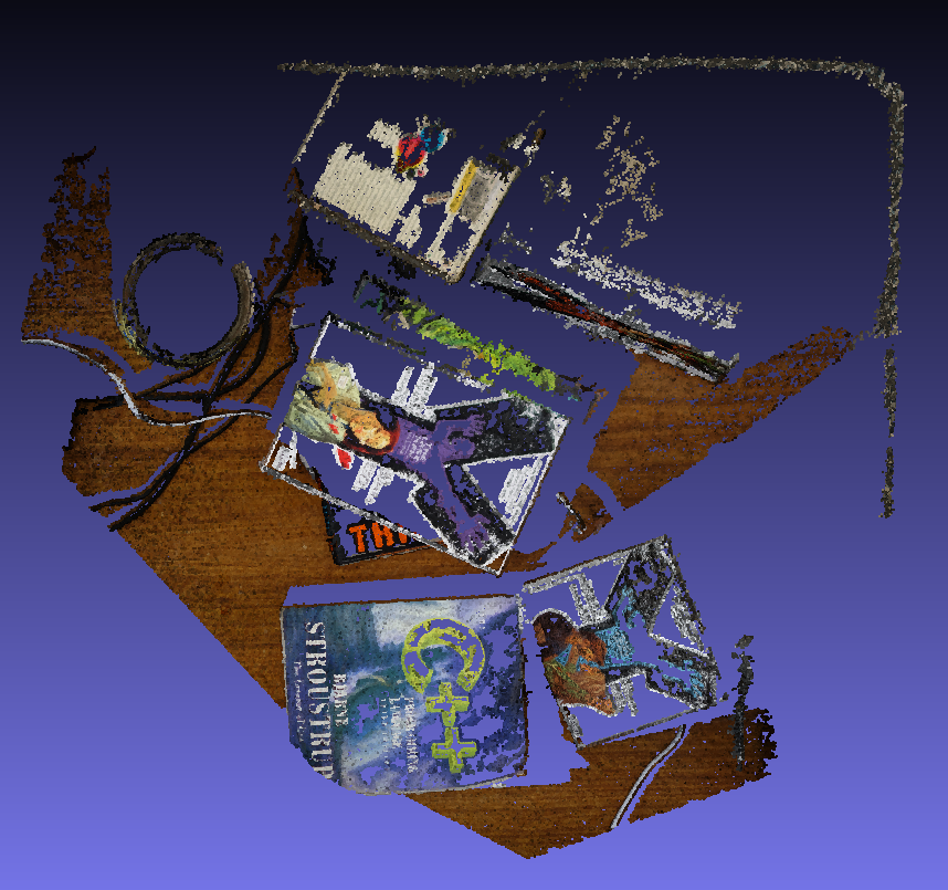
Here’s a screenshot of the output point cloud in Meshlab.
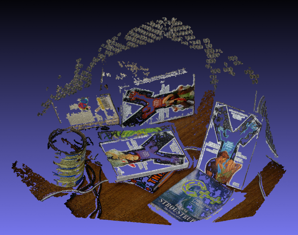
If you set Meshlab to display in orthographic mode you can see the walls make a right angle.
References
http://rpg.ifi.uzh.ch/visual_odometry_tutorial.html
Thanks for good intro into sfm. I am just now learning the basics of openCV as a hobby. I am still confused by terminology such as camera pose. In opencv it seems that the convention is that [R|T] is the projection matrix used to go from homogeneous world cords to homogeneous normalized camera coordinates. It is my understanding that the recoverPose function returns the R and T such that the projection matrix is [R|T]. So I feed the triangulatePoints the function projection matrix = K[R|T] where K is the intrinsic camera matrix, rather than using K[Rt|-RtT] as you mention. So I worry I am not understanding the conventions used by the openCV functions recoverPose and triangulatePoints?
My understanding is that the camera pose relates camera movement, where as the projection operates on 3d points, so they should have different representation. A simple example you can think of is a camera that moves in the x direction by 1 unit with no rotation. So the camera pose is R = identity, t = [1,0,0]. If we are looking at a bunch of 3d points in front of us, then by moving the camera right, we expect the points to move left, resulting in the projection matrix [R=identity | t=[-1,0,0]].
Can you confirm you are getting correct results with the what you are doing?
Thanks much. That makes sense that the term “camera pose” refers to the location and orientation of the camera as opposed to coordinates in the camera’s reference frame given by the projection matrix. I guess my confusion stems from the fact that pose could refer to the orientation of an object relative to the camera (maybe that would be called “object pose”. I recently ran camera calibration for the 1st time using a checkerboard and in some documentation, pose referred to the pose of the checkerboard as it is moved relative to a fixed camera. Also, I learned about the essential matrix and how it is defined in terms of the camera coordinates. I ran the findEssentialMatrix(pts1, pts2, …..) function with a 5×5 grid of simulated point correspondences (simulated moving the camera to the right by shifting the second image(normalized) coordinates to the left by an arbitrary 0.1 units and then added a small bit of forward motion by magnifying the cords by factor of 1.02). So this simulates moving camera by (dx=0.1, dy=0, dz= 1.0-(1.0/1.02) = 0.01961). I checked that the resulting essential matrix E honored x2 dot E*x1 = 0 for all the point correspondences. So I feel good about the E matrix I got. Then I ran recoverPose(E, pts1, pts2….) and got the identity matrix for R (as expected – no rotation, so it choose the correct R from the 2 possible ones) and it output T = (-0.1, 0, -0.01961) which is consistent with [R|T] of the cam2 projection matrix (cam1 matrix being [I|0] in my way of thinking about it). So this is why I am confused, since recoverPose seemed to return R, T of the projection matrix for cam2 instead of the pose of camera2. But I may be thinking about this the wrong way, and the documentation just says that recoverPose recovers the relative rotation and translation of two cameras. Well, there are many possible meanings for that and the only thing I am sure of is that my head is spinning and translating or is that translating then spinning which to me appears as the world reverse spinning and negative translating or is that negative translating and reverse spinning respectively…….
Thanks for the materials. Can I ask what platform are you using ? I found lots of difficulties making GTSAM and PMVS works on windows…
Ubuntu 16.04. A lot of the libraries that it depends on are developed for Unix’ish platforms.
Hi, I just started learning about SFM and stumbled on your articles. I have tried your “RunSFM” and it works great! I’m currently trying to compile the “SFM_example” listed in this article, but can’t seem to find the “compile.sh” script listed anywhere to create the “./main” executable. Since it isn’t provided on the github page, should I try some other way to create the executable to run the “SFM_example”?
Thanks in advance!
Oops, do a git pull now.
Hey – I’m trying to do something similar – using gtsam (and some other bundle adjustment libs) for structure for motion – The code is here https://github.com/maym86/visual_odometry/tree/gtsam-test/src
When I run gtsam on a set of sliding window frame the pose just starts jumping wildly. I have had the same issue with other bundle adjustment libraries including pba and sba. I have carefully looked at your code and cant see any obvious differences in the steps.
Your explanation of the K[Rt|-RtT] vs K[R|T] was very useful for recovering the 3d points correctly.
Any tips or insight into why why using bundle adjustment on consecutive frames to refine pose might lead to seemingly random jumps would be very helpful.
Thanks for any tips you can provide.
Mike
Do you get bad pose even on the first call to bundle adjustment?
I have an isolated test that often works well with 3-5 frames where I call ba only once.
By which I mean I think it is working correctly for the first step or a single call to bundle adjustment.
Does the code work correctly without bundle adjustment?
Yep – without BA I get a pretty decent trajectory that roughly matches the path of the kitti data. There are some scale issues but the path is pretty close to expected.
Is the graph getting optimized at all eg. final err < initial err ?
Yeah it looks ok. The error is shrinking and sometimes I get a error regarding InconsistentEliminationRequested
I0922 14:45:04.785989 16580 bundle_adjustment.cpp:329] initial graph error = 1.11633e+07
I0922 14:45:04.789669 16580 bundle_adjustment.cpp:330] final graph error = 5.16594
I0922 14:45:04.972045 16580 bundle_adjustment.cpp:240] 340 7
I0922 14:45:05.318065 16580 bundle_adjustment.cpp:329] initial graph error = 3.71153e+06
I0922 14:45:05.322494 16580 bundle_adjustment.cpp:330] final graph error = 3.15462
I0922 14:45:05.563437 16580 bundle_adjustment.cpp:240] 313 7
I0922 14:45:05.762372 16580 bundle_adjustment.cpp:329] initial graph error = 5915.4
I0922 14:45:05.766343 16580 bundle_adjustment.cpp:330] final graph error = 2.70726
I0922 14:45:05.999307 16580 bundle_adjustment.cpp:240] 207 7
terminate called after throwing an instance of ‘gtsam::InconsistentEliminationRequested’
what(): An inference algorithm was called with inconsistent arguments. The
factor graph, ordering, or variable index were inconsistent with each
other, or a full elimination routine was called with an ordering that
does not include all of the variables.
Your initial error is very high, which may suggest your initialization is incorrect. Are the landmarks’ position transformed to the world frame?
With BA results look like this
https://imgur.com/a/JwrVYAU
Yeah it does seem big – aggregation of local [R|t] into a global pose is here:
https://github.com/maym86/visual_odometry/blob/823b723c8f387931e79a64a3a27dda3b2d3f0f47/src/visual_odometry/vo_pose.h#L37
Should I be doing a conversion into a different coordinate system before running BA? It seems like you just use the aggregated pose directly in your code.
My function to get the projection matrix is here: https://github.com/maym86/visual_odometry/blob/823b723c8f387931e79a64a3a27dda3b2d3f0f47/src/sfm/triangulation.cpp#L34
Really appreciate you taking the time to help.
Something is up – you are correct about a coordinate issue I think but I am still unsure how to fix it.
I used this code to reproject the 3D points and measure the error:
std::vector image_points;
std::vector object_points;
object_points.push_back(point_3d);
cv::projectPoints(object_points ,R_[cams[0]],t_[cams[0]], K_, cv::noArray(), image_points );
LOG(INFO) << image_points[0] << points[0] << cv::norm(cv::Mat(image_points[0]) – cv::Mat(points[0]));
When the camera is at the origin things seem close to ok but when the camera is offset from the origin the re-projection error is big (this is a offset of 20 from the origin):
[Reprojected point][original 2d point] error
[1092.61, 603.977][644.653, 35.8443]723.49
I0923 14:47:12.596024 27328 bundle_adjustment.cpp:119] [942.215, 641.026][60.5783, 36.5807]1068.94
I0923 14:47:12.596168 27328 bundle_adjustment.cpp:119] [1090.97, 605.376][647.623, 40.9823]717.704
I0923 14:47:12.596267 27328 bundle_adjustment.cpp:119] [1163.77, 607.482][824.832, 43.1621]658.282
I0923 14:47:12.596367 27328 bundle_adjustment.cpp:119] [1022.97, 546.965][589.961, 46.5968]661.714
I’m assuming you are passing the camera pose to cv::projectPoints, I think this is not correct, try using the inverse camera pose.
Do you mean [Rt|-RtT]?
That also gives some weird results although the first one looks correct but negated.
I0923 15:36:34.658128 31617 bundle_adjustment.cpp:123] [-212.675, -91.2379][214.516, 91.424]464.604
I0923 15:36:34.683930 31617 bundle_adjustment.cpp:123] [670.244, 135.415][462.161, 93.5236]212.258
I0923 15:36:34.743180 31617 bundle_adjustment.cpp:138] 2 2
I0923 15:36:34.933590 31617 bundle_adjustment.cpp:123] [73.5754, 4.15234][837.557, 53.3322]765.563
I0923 15:36:34.934371 31617 bundle_adjustment.cpp:123] [-212.675, -91.2379][214.516, 91.424]464.604
I0923 15:36:34.939889 31617 bundle_adjustment.cpp:123] [-934.661, -380.345][679.961, 275.542]1742.75
I0923 15:36:34.948380 31617 bundle_adjustment.cpp:123] [-592.694, -240.929][677.388, 274.273]1370.6
I0923 15:36:34.950469 31617 bundle_adjustment.cpp:123] [-186.161, -89.5969][250.857, 118.928]484.218
Actually my mistake – with inversion the results look correct
I0923 15:52:11.798718 783 bundle_adjustment.cpp:124] [645.847, 35.9239][644.653, 35.8443]1.19662
I0923 15:52:11.799306 783 bundle_adjustment.cpp:124] [60.1977, 36.3452][60.5783, 36.5807]0.44758
I0923 15:52:11.799427 783 bundle_adjustment.cpp:124] [640.557, 40.523][647.623, 40.9823]7.08077
I0923 15:52:11.799510 783 bundle_adjustment.cpp:124] [849.549, 44.5258][824.832, 43.1621]24.7544
I0923 15:52:11.799584 783 bundle_adjustment.cpp:124] [593.277, 46.8743][589.961, 46.5968]3.32732
I0923 15:52:11.799654 783 bundle_adjustment.cpp:124] [264.474, 50.9974][253.934, 48.938]10.7397
I0923 15:52:11.799738 783 bundle_adjustment.cpp:124] [842.409, 53.0934][830.747, 52.3282]11.6874
I0923 15:52:11.799810 783 bundle_adjustment.cpp:124] [865.235, 55.1618][837.557, 53.3322]27.7384
I0923 15:52:11.799897 783 bundle_adjustment.cpp:124] [712.484, 53.6035][767.298, 57.8351]54.9762
I0923 15:52:11.799979 783 bundle_adjustment.cpp:124] [219.821, 67.4852][202.325, 62.1072]18.3042
Hello, I’m very interested in sfm and your explanation on this subject is very helpful.
I want to ask about implementation of sfm for another dataset. I used a dinosaur dataset (http://www.robots.ox.ac.uk/~vgg/data/data-mview.html).
Implementation in python, opencv and BA with g2opy. After triangulation I tried to show the points in 3d . For 3 frames I got 3 dinos, for 4 frames I got 7 dinos.
Do you have any suggestion on how to get 1 point cloud for the entire set of frames?
Thank you
I don’t have enough information to answer this. Is this a simple file concatenation problem?
Hi, Thank you for your fast replay.
I don’t think this concatenation problem,
I tried to run this dataset in colmap and it worked fine.
I work with this pipeline:
starting with Feature extraction for a sequential couple of frames each time, I used ORB detector.
after that, I did Feature matching, each image matching with the next one,
next I calculated Essential matrix and recoverPose (using opencv) for the two first frames.
then I used triangulation to get 3d points from 2d points.
I got P for the first frame equals to K[I(3X3)|0] and for the second frame I got [R|t] I calculated R and t .
After that, I implemented your motion estimation using a relative scale for other frames.
I used g2o for a basic Bundle Adjustment,
When I show the 3d points after triangulation and after BA I get multiple dinosaurs instead of one.
I think the problem is in the relative scale or the BA. Maybe I should implement a local and a global BA? other improvements in the BA? Do you have another reference for the relative scale?
Thank you very much
Are you correctly tracking the same features across each image for as long as possible and creating the right graph to reflect this?
I think so,
I run a script that tests matching for each image with all the other images. The matching of an image with its 2 following images contains a lot of features, but the matching with the other images has fewer features matched, do you think this can be a problem?
I create a global object that saves for each feature its place in all the images in which it was detected in.
After that, I create the graph with this global object, for each camera pose I create a vertex as well as for each feature, because each feature is a landmark, so two camera poses are connected by a feature(landmark).
Check to make sure your landmarks are seen by 3 or more cameras. Two views is not enough to constrain the problem.
it happens to some images . Don’t know why. After calculate triangulation of 4 images it show correct 3d view of object. But after 4 images it become messy. Point become gap in z – index and bigger version of pervious point 3d point cloud.
I use only in landmarks that seen in 3 cameras, but this is the problem there are no landmarks that seen on more than 3 cameras.
if this step works well, you have an idea why this does not work?
maybe improve the Bundle Adjustment?
Hi, thanks for the great tutorial. Please correct me if I am wrong. The pipeline for image 0 and image 1 would be –
Match features –> find essential matrix –> find projection matrix –> triangulate points
The pipeline for the image 1 and image 2 would be –
Use features with triangulated points from image 1 –> compute matches for these features in image 2 –> find essential matrix –> find projection matrix –> triangulate points –> use one pair of triangulated points from the previous step and one pair from the current step to determine scale –> update current projection matrix
Also, can you please tell me why you accumulate transforms in your code?
To keep the poses in a consistent global frame.
Yeah that sounds about right.
Thank you for the great tutorial! This was very helpful. One question though, how can I display the camera’s motion and orientation in world coordinates?
Assuming you have the camera as a pose matrix (if it’s in projection form invert it) then you can read the values directly from the matrix [R | t]. R is the rotation t is the position in world.
Thank you for the reply. One more question, if you have the time. Are you trying to get all the matches between all permutations of image pairs before estimating the camera motion and triangulating points in 3D?
That is correct.
Hi,
Thanks for such a wonderful contribution. I am trying to do the same but with OpenCV Viz for visualization and G2O for Bundle Adjustment. But the problem I am facing is the pose and the point cloud is upside down. In OpenCV viz the Axis is X is positive to the right, Y is positive to the up and Z is positive towards me. Can you please help me to sort out the issue kindly?
Maybe flip both y, z of your resulting point cloud?
Hmm. You are right sir what I have found is the Viz modules Y axis positive towards above and X is positive towards left but in Pinhole camera model things are different Y is positive towards bottom and X is positive towards right. Causing the issue of direction mismatch between the result and the viewer.
So I have flipped the Viz module accordingly to match Pinhole model solved the issue for me. Although, thank you again for such an nice example of SFM and your reply.
Hello, I was trying to run you example without changes but I have segmentation fault on Bundle Adjustment more precisely in “result = LevenbergMarquardtOptimizer(graph, initial).optimize();” any idea why thats happening?
What version of GTSAM are you using? Maybe I can replicate it.
the most recent ‘gtsam-4.2a5’ with opencv4
I’m trying to contact you by email (nghiaho12@yahoo.com) could you answer me there? Thank you very much
I have the same problem with GTSAM. I use GTSAM 4.1.1. I built success your code but when run it, always segmentation fault.
There’s a bug in GTSAM https://github.com/borglab/gtsam/issues/75
The work around that works for me is to disable GTSAM_BUILD_WITH_MARCH_NATIVE when compiling GTSAM.