Category Archives: Technical

A bunch of technical posts to help me remember useful stuff, should I become senile in the future.

Computer vision on the FPGA

This is a follow up on my previous post about my first step into the FPGA world. In this post I’ll give a high level description of my implementation of a simple 3×3 convolution image filtering circuit. It does not aim to be fast or efficient, just something that works. If you want to know anything in more detail look at the code or leave a comment below.

I’ll assume the reader is familiar with 3×3 filters like the Sobel edge detector. In this project l implement the Laplacian filter, but you can easily change the filter by changing the hard coded values inside the Verilog file.

Below is a high level overview of my FPGA design. I’ve omitted the input/output pins for each of the block component for simplicity.

fpga_3x3_filter

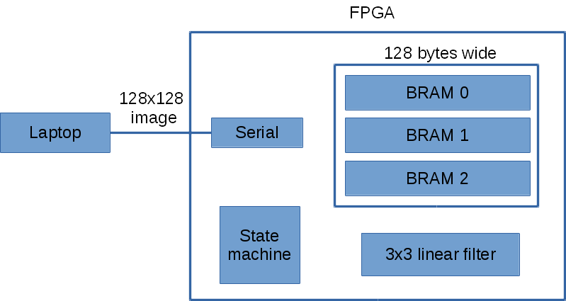
The laptop sends the image over the serial one row at a time to the FPGA. The FPGA then immediately sends the processed pixel row back to the laptop. I chose this design because it only requires three row buffers on the FPGA. The Basys2  has 72Kbits of fast RAM.  For an image width of 128 pixels, it only requires 128×3 = 384 bytes of RAM.

The state machine handles all the logic between the serial, BRAM and 3×3 linear filter.

I decided to use serial for communication between the laptop and FPGA because it was simpler, though slower. I did however manage to crank up the serial speed to 1.5 Mbit by adding an external 100Mhz crystal oscillator. Using the default 50Mhz oscillator on the Basys2 I can get up to 1 Mbit.

I use three banks of dual port BRAM (block RAM). The dual port configuration allows two simultaneously read/write to the same BRAM. This allows me to read 3×2=6 pixels  in one clock cycle. For 3×3=9 pixels it takes two clock cycles. I could do better by making the read operation return more pixels. The three banks of BRAM act as a circular buffer. There’s some logic in the state machine that keeps track of which bank of BRAM to use for a given input pixel row.

Right now with the my current BRAM configuration and 3×3 filter implementation it takes 5 clock cycles to process a single pixel, excluding serial reading/writing. If you include the serial transmission overhead then it takes about 380 ms on my laptop to process a 128×128 grey image.

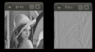
Below is the result of the Laplacian filter on Lena. I ignored the pixels on the border of the image, so the final image is 126×126.

lena_fpga_3x3

Download

FPGA_3x3_filter.zip

The zip file contains only the necessary Verilog code and a main.cpp for sending the image. The main.cpp requires OpenCV for display. I omitted any Xilinx ISE specific project files to keep it simple. But if there’s any missing files let me know. Your input image must be 128×128 in size to work.

WordPress malware

My site got hit hard with some malicious WordPress trojans (possibly via plugins) and caused the site to get suspended. It’s back up now with a fresh theme. I deleted every plugin and re-installed only the necessary ones. Code highlighting isn’t enabled yet, can’t rememeber what I last installed.

First trip to FPGA land

Been a while since I last posted anything. I’ve been pretty busy at my new job but managed to find some spare time to learn about FPGA. I wanted to see what all the rage is about. I purchased a Digilent Basys2 not too long ago to play with. It’s an entry board under $100, perfect for a noob like myself. Below is the Basys2 board. I bought a serial module so I can communicate using the latop, shown in the top left connected to the red USB cable.

fpga

For the first two weeks I went through the digital design book on Digilent’s site to brush up on stuff I should have remembered during my undergrad but didn’t. It’s a pretty good book for a quick intro to the basic building blocks with example code in Verilog/VHDL. I chose the Verilog book over VHDL because I found it easier to read, and less typing.

I then spent the next two or three weeks or so implementing a simple RS232 receiver/transmitter, with help from here. Boy, was that a frustrating project, but I felt I learnt a lot from that experience. That small project helped me learned about RS232 protocol, Verilog, Xilinx ISE and iSim.

Overall, I’m enjoying FPGA land so far despite how difficult it can be. There’s something about being intimately closer to the hardware that I find appealing.

My original intention for learning the FPGA is for image processing and computer vision tasks. The Basys2 doesn’t have a direct interface for a camera so for now I’ll stick to using the serial port to send images as proof of concept. Maybe I’ll upgrade to a board with a camera interface down the track.

I recently wrote a simple 3×3 filter Verilog module to start of with. It’s a discrete 3×3 Laplacian filter.

module filter3x3(
input wire clk,
input wire [7:0] in0,
input wire [7:0] in1,
input wire [7:0] in2,
input wire [7:0] in3,
input wire [7:0] in4,
input wire [7:0] in5,
input wire [7:0] in6,
input wire [7:0] in7,
input wire [7:0] in8,
output reg signed [15:0] q
    );

always @ (posedge clk)
begin
    q <= in0 + in1 + in2 +
          in3 - in4*8 + in5 +
          in6 + in7 + in8;
end

endmodule

This module takes as input 8 unsigned bytes and multiples with the 3×3 kernel [1 1 1; 1 -8 1; 1 1 1] and sums the output to q. It is meant to do this in one clock cycle. I’ve tested it in simulation and it checks out. Next step is to hook up to my serial port module and start filtering images. Stay tune!

Fixing vibration on Taig headstock

I’ve been using the Taig for a few weeks now and had noticed significant vibration on the headstock. I don’t have access to another Taig to compare to see if it’s normal but it definitely “felt” too much. Last week I finally got around to addressing it.

The first thing I noticed was the pulley on the motor being slightly wonky (not running true). After a call to Taig they sent me a replacement pulley. They were very helpful and knowledgeable and know their stuff. They suggested other factors that I can check to help with the vibration issue.

When the pulley arrived I replaced the old one and re-aligned the belt using a parallel and eye balling. Sadly, this did not fix the problem. Then I remember one suggestion by the guys at Taig. He said where the motor mount aligns to the 1×1 inch steel block might not be perfectly flat and could cause vibration because the pulley would be on a slight angle. Guess what, he’s right! With the spindle running at 10,000RPM or so, I applied some force to the motor with my hand and noticed the vibration varied a lot.

This is the hack that I settled on. Every time I adjust the spindle speed I screw the far back screw tight, while the other one is lightly tightened. Just enough so the motor doesn’t twist. I got curious and hooked up a dial indicator to the headstock. As I tightened the screw I could see the vibration ramp up.

Here are two pics that summarize the problem (I think) and the hack fix.

taig_vibration2

taig_vibration1

Your situation may differ. Play around with the screws and see what happens.For now it seems to do the job. Vibration is at a minimum, I’m happy.

Machining an aluminium block on the Taig CNC mill

I’ve recently had the chance to get back into some CNC’ing with the Taig CNC mill at work. This is the first time I’ve used the Taig and I must say it’s a pretty slick machine for its size. I was tasked with machining out a rectangular block as an initial step for a more complex part. I thought given how much beefier this CNC is compared to my home made ones it should be a walk in the park. It could not be further from the truth!

I’ve consulted many online/offline calculators and read as much posts from other people’s experience to hone in a setting I was happy with. I’ve lost count of how many end mills I’ve broken along the way! Fortunately I ordered some fairly inexpensive end mills to play with so it wasn’t too bad.

The two most common end mills I’ve used are the 3/8″ 1 inch length of cut and a 1/8″ 1 inch length of cut, both 2 flutes and both from Kodiak. To machine out the block I saved some time by removing most of the material with a drop saw (miter saw). This meant less work for the 3/8″ end mill. Here’s a summary of what I used

3/8″ end mill 2 flutes, 1 inch length of cut

  • RPM: ~ 3000
  • feed rate: 150 mm/min (~6 ipm)
  • plunge rate: 50 mm/min (~2 ipm)
  • depth per pass: 2 mm (0.0787″)

1/8″ end mill 2 flutes, 1 inch length of cut

  • RPM: ~10,000
  • feed rate: 500 mm/min (~20 ipm)
  • plunge rate: 200 mm/min
  • depth per pass: 0.5 mm (~ 0.02″)

The 1/8″ end mill isn’t used to machine the block but for another job.

Here is my very basic Taig setup. It is bolted to the table top.

IMGP6597

There’s no automatic coolant or air flow installed so I’m doing it manually by hand. Not ideal, but does the job and keeps me alert! I’m using Kool Mist 77. That’s the 3/8″ end mill in the pic. It’s about the biggest end mill that is practical on the Taig. I’ve added rubber bands to the safety goggle to stop it from falling off my head because I wear glasses.

Below shows one side of the block I milled. The surface is very smooth to touch.

IMGP6585

But when looking on the other side, where the cutter is going in the Y direction it shows some wavy patterns?! Not sure what’s going on there. It didn’t mess up the overall job because it was still smooth enough that I could align it on a vise. Still, would like to know what’s going on.

IMGP6612

Here are some things I’ve learnt along the way

Clear those chips!

I originally only used Kool Mist and just squirting extra hard to clear the chips. This got a bit tiring and I wasn’t doing such a great job during deeper cuts. Adding the air hose makes life much easier. I found 20-30 PSI was enough to clear the chips.

Take care when plunging

I’ve read the 2 flutes can handle plunging okay but I always find it struggles if you are not careful. The sound it makes when you plunge can be pretty brutal to the ear, which is why I tend to go conservative. I usually set the plunge rate to half the feed rate and take off 50 mm/min. If I’m doing a job in CamBam I use the spiral plunging option, which does a very gradual plunge while moving the cutter in a spiral. Rather than a straight vertical plunge, which makes it harder to clear chips at the bottom. I’ve broken many smaller end mills doing straight plunges. I once did a plunge with the 3/8″ end mill that was a bit too fast and it completely stalled the motor.

I probably should look at per-drilling holes to minimize plunging.

Go easy!

I’ve found a lot of the answers from the feed rate calculators rather ambitious for the Taig. They tend to assume you got a big ass CNC with crazy horse power. Some of the calculators I’ve used take into consideration the tool deflection and horse power, which is an improvement. But at the end of the day the Taig is a tiny desktop CNC weighing at something like 38kg. So know its limits!

3D camera rig

Been helping out a mate with setting up a 3D camera rig. It’s been a while since I’ve done mechanical work but it’s great to get dirty with machinery again!

Here’s a video of the camera rig being set up. This video is a bit dated, the current setup has lots of lighting stands not shown.

Here’s a result of my head using Agisoft Photocan. Looks pretty good so far!

https://sketchfab.com/models/78c7d06c5d5a482e95032ad0eba7eac2

ICRA 2014 here we come!

Woohoo our paper “Localization on Freeways using the Horizon Line Signature” got accepted for ICRA 2014 Workshop on Visual Place Recognition in Changing Environments! Now I just need to sort out funding. The conference registration is over $1000! Damn, that’s going to hurt my pocket …

This is the new video we’ll be showing at our poster stand

Old school voxel carving

I’ve been working on an old school (circa early 90s) method of creating 3D models called voxel carving. As a first attempt I’m using an academic dataset that comes with camera projection matrices provided. The dataset is from

http://www.cs.wustl.edu/~furukawa/research/mview/index.html

specifically the Predator dataset (I have a thing for Predator).

Here it is in action

Screen recording was done using SimpleScreenRecorder, which was slick and easy to use.

Download VoxelCarving.tar.gz

You will need OpenCV installed and the Predator images. Instructions can be found in the README.txt.

Fun with seam cut and graph cut

This fun little project was inspired by a forum post for the Coursera course Discrete Inference and Learning in Artificial Vision. 

I use the method outlined in Graphcut Textures: Image and Video Synthesis Using Graph Cuts.

The toy problem is as follows. Given two images overlaid on top of each, with say a 50% overlap, find the best seam cut through the top most image to produce the best “blended” looking image. No actual alpha blending is performed though!

This is a task that can be done physically with two photos and a pair of scissors.

The problem is illustrated with the example below. Here the second image I want to blend with is a duplicate of the first image. The aim is to find a suitable seam cut in the top image such that when I merge the two images it produces the smoothest transition. This may seem unintuitive without alpha blending but it possible depending on the image, not all type of images will work with this method.

apple_seamcut

By formulating the problem as a graph cut problem we get the following result.

graphcut_apple

and the actual seam cut in thin red line. You might have to squint.

graphcut_and_cut_line

If you look closely you’ll see some strangeness at the seam, it’s not perfect. But from a distance it’s pretty convincing.

Here are a more examples using the same method as above, that is: duplicate the input image, shift by 50% in the x direction, find the seam cut in the top layer image.

strawberry

graphcut_strawberry

This one is very realistic.

Who likes penguins?

penguins-795082

graphcut_penguin

Code

SeamCut.tar.gz

You’ll need OpenCV 2.x install.

I’ve also included the maxflow library from http://vision.csd.uwo.ca/code/ for convenience.

To run call

$ ./SeamCut img.jpg

Simple video stabilization using OpenCV

I’ve been mucking around with video stabilization for the past two weeks after a masters student got me interested in the topic. The algorithm is pretty simple yet produces surprisingly good stabilization for panning videos and forwarding moving (eg. on a motorbike looking ahead). The algorithm works as follows:

  1. Find the transformation from previous to current frame using optical flow for all frames. The transformation only consists of three parameters: dx, dy, da (angle). Basically, a rigid Euclidean transform, no scaling, no sharing.
  2. Accumulate the transformations to get the “trajectory” for x, y, angle, at each frame.
  3. Smooth out the trajectory using a sliding average window. The user defines the window radius, where the radius is the number of frames used for smoothing.
  4. Create a new transformation such that new_transformation = transformation + (smoothed_trajectory – trajectory).
  5. Apply the new transformation to the video.

Here’s an example video of the algorithm in action using a smoothing radius of +- 30 frames.

We can see what’s happening under the hood by plotting some graphs for each of the steps mentioned above on the example video.

Step 1

This graph shows the dx, dy transformation for previous to current frame, at each frame. I’ve omitted da (angle) because it’s not particularly interesting for this video since there is very little rotation. You can see it’s quite a bumpy graph, which correlates with our observation of the video being shaky, though still orders of magnitude better than Hollywood’s shaky cam effect. I’m looking at you Bourne Supremacy.

transformation

Step 2 and 3

I’ve shown both the accumulated x and y, and their smoothed version so you get a better idea of what the smoothing is doing. The red is the original trajectory and the green is the smoothed trajectory.

It is worth noting that the trajectory is a rather abstract quantity that doesn’t necessarily have a direct relationship to the motion induced by the camera. For a simple panning scene with static objects it probably has a direct relationship with the absolute position of the image but for scenes with a forward moving camera, eg. on a car, then it’s hard to see any.

The important thing is that the trajectory can be smoothed, even if it doesn’t have any physical interpretation.

smoothed_trajectory_x

smoothed_trajectory_y

Step 4

This is the final transformation applied to the video.

smoothed_transformation

Code

videostab.cpp

videostabKalman.cpp (live version by Chen Jia using a Kalman Filter)

You just need OpenCV 2.x or above.

Once compile run it from the command line via

./videostab input.avi

More videos

Footages I took during my travels.