CIFAR10 with fastai
Numpy images with fastai
Using the iPhone TrueDepth Camera as a 3D scanner
A friend of mine from PunkOffice (punkoffice.com) recently hit me up and asked if I knew how to register a bunch of point clouds from his shiny Apply iPhone 11 that comes with a TrueDepth camera. He was interested in using it as a portable 3D scanner. Why yes I do! At least I did over a decade ago for my PhD. Back then I used the popular ICP (Iterative Closest Point) algorithm to do point-to-point registration. It did the job. But I wasn’t in the mood to reinvent the wheel again. So instead I searched for existing Python libraries that would get the job done with the least amount of effort. In my search I came across the Open3D library (http://open3d.org) that comes with Python bindings. This library includes file loaders for various 3D formats, a handful of registration methods, and a visualizer. Perfect!
What was meant to be a quick proof of concept eventually evolved into a mini R&D project as I sought for better registration accuracy!
The code is at the bottom of the page.
Problem we’re trying to solve
Essentially we’re trying to solve for the camera poses, that is its orientation and translation in 3D space. If we know the camera poses then creating a 3D point cloud from the individual captures is easy, we just project the 3D point out at that pose and we’re done. To do this we need to know the TruthDepth camera’s calibration and a dataset to work with.
Apple TrueDepth camera calibration
The first step was to gather any useful information about the TruthDepth camera. Apple has an API that allows you to query calibrationn data of the camera. I told my friend what I was looking for and he came back with the following
- raw 640×480 depth maps (16bit float)
- raw 640x480x3 RGB images (8bit)
- camera intrinsics for 12MP camera
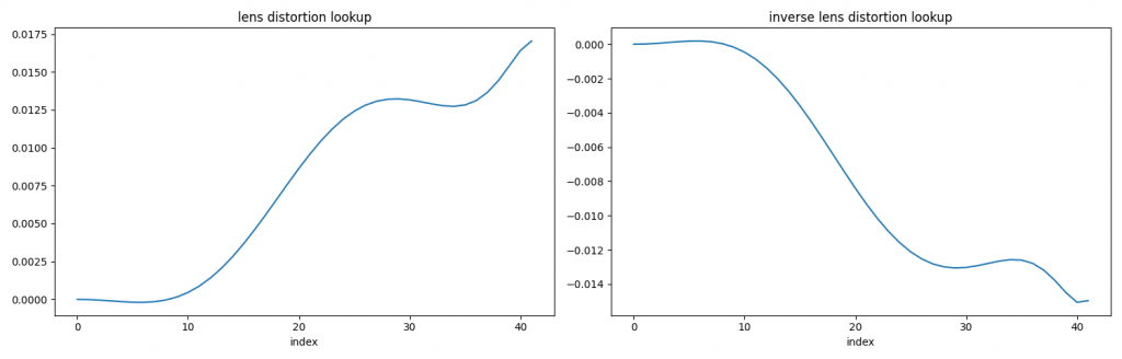
- lens distortion lookup (vector of 42 floats)
- inverse lens distortion lookup (vector of 42 floats)
Some intrinsic values
- image width: 4032
- image height: 3024
- fx: 2739.79 (focal)
- fy: 2739.79 (focal)
- cx: 2029.73 (center x)
- cy: 1512.20 (center y)
This is fantastic, because it means I don’t have to do a checkerboard calibration to learn the intrinsics. Everything we need is provided by the API. Sweet!
The camera intrinsics is for a 12MP image, but we’re given a 640×480 image. So what do we do? The 640×480 is simply a scaled version of the 12MP image, meaning we can scale down the intrinsics as well. The 12MP image aspect ratio is 4032/3204 = 1.3333, which is identical to 640/480 = 1.3333. The scaling factor is 640/4032 = 0.15873. So we can scale [fx, fy, cx, cy] by this value. This gives the effective intrinisc as
- image width: 640
- image height: 480
- fx: 434.89
- fy: 434.89
- cx: 322.18
- cy: 240.03
Now the distortion is interesting. This is not the usual radial distortion polynomial paramterization. Instead it’s a lookup table to determine how much scaling to apply to the radius. This is the first time I’ve come across this kind of expression for distortion. A plot of the distortion lookup is shown below
Here’s some pseudo code to convert an undistorted point to distorted point
def undistort_to_distort(x, y):
  xp = x - cx
  yp = y - cy
  radius = sqrt(xp*xp + yp*yp)
  normalized_radius = radius / max_radius

  idx = normalized_radius*len(inv_lens_distortion_lookup)
  scale = 1 + interpolate(inv_lens_distortion_lookup, idx)

  x_distorted = xp*scale + cx
  y_distorted = yp*scale + cy

  return x_distorted, y_distorted
idx will be a float and you should interpolate for the correct value, rather than round to the nearest integer. I used linear interpolation. To go from distorted to undistorted switch inv_lens_distortion_lookup with lens_distortion_lookup.
With a calibrated camera, we can project a 2D point to 3D as follows.
def project_to_3d(x, y, depth):
  xp = (x - xc)/fx * depth
  yp = (y - yc)/fy * depth
  zp = depth

  return [xp, yp, zp]
I found these links helpful when writing up this section.
- https://frost-lee.github.io/rgbd-iphone/
- https://developer.apple.com/documentation/avfoundation/avcameracalibrationdata
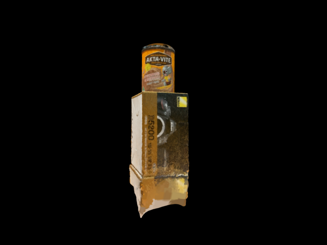
Dataset
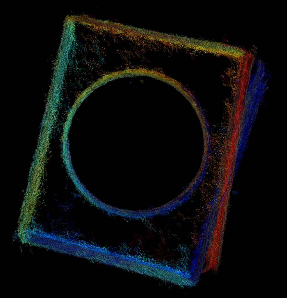
The dataset I got from my friend consists of 40 captures, which includes both RGB images and depth maps as shown below. I’m showing a gray image to save file space and I segmented the depth map to isolate the objects so you can see it better. There’s a box with a tin can on top, which are two simple shapes that will make it easy to compare results later on. The camera does a 360 or so degree pan around the object, which we’ll exploit later on as well.
Method #1 – Sequential ICP
The simplest method I could think of is sequential ICP. In this method the current point cloud is registered to the previous. I used Open3D’s point-to-plane variant of ICP, which claims better performance than point-to-point ICP. ICP requires you to provide an initial guess of the transform between the point clouds. Since I don’t have any extra information I used the identity matrix, basically assuming no movement between the captures, which of course isn’t true but it’s a good enough guess.
Below shows a top down view of the box and can. You can some misalignment of the box on the right side. This will be our baseline.
Method #2 – Sequential vision based
There are two drawbacks with the sequential ICP approach. First, using 3D points alone can not resolve geometric ambiguities. For example, if we were to capture a sequence of a flat wall, ICP would struggle to find the correct transform. Second, ICP needs an initial transform to boot strap the process.
To address these shortcomings ‘ll be using both the image and depth data. The image data is richer for tracking visual features. Here is an outline the approach
1. Track 2D SIFT features from current to previous frame
2. Use the fundmanmetal matrix to filter out bad matches
3. Project the remaining 2D points to 3D
4. Find the rigid transform between current and previous 3D points
We now have a good estimate for the transform between camera poses, rather than assume identity transform like with ICP!
The advantage estimating the transform in 3D is it’s much easier and possibly than traditional 2D approaches. The rigid transform can be calculated using a closed form solution. The traditional 2D approach requires calculating the essential matrix, estimating 3D points, solving PnP, … And for a monocular camera it’s even trickier!
Here’s the result of the sequential vision based approach
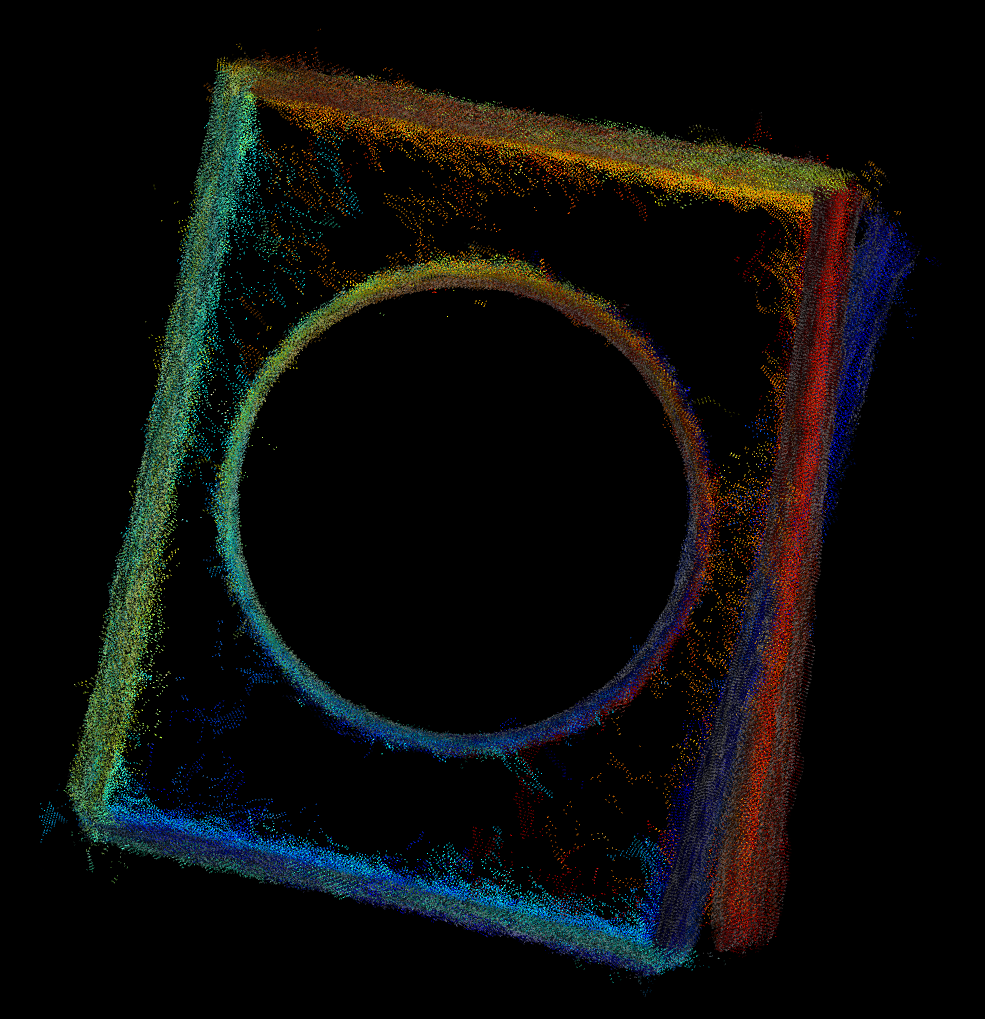
Hmm no noticeable improvement. Sad face. Still the same problem. Fundamentally, our simplistic approach of registering current to previous introduces a small amount of drift over each capture.
Oh fun fact, the SIFT patent expired some time early 2020! It got moved out of OpenCV’s non-free module and is now back in the features2d module.
Method #3 – Sequential vision based with loop closure detection
To reduce the effect of drift and improve registration we can exploit the knowledge that the last capture’s pose is similar to one of the earlier capture, as the camera loops back around the object. Once we find the loop closure match and the transform between them we can formulate this as a pose graph, plus feature matching constraints, and apply an optimization. Pose graph optimization is commonly used in the robotics community to solve for SLAM (simultaneous localization and mapping) type of problems. There are 3 main ingredients for this optimization
1. define the parameters to be optimized
2. define the cost function (constraint)
3. provide good initial estimates of the parameters
As mentioned earlier, we’re interested in solving for the camera poses (rotation, translation). These are the parameters we’re optimizing for. I chose to represent rotation as a Quaternion (4D vector) and translation as a 3D vector (xyz). So a total of 7 parameters for each camera. It’s also common to represent the rotation using an axis-angle parameterization, such that it’s a 3D vector. This will be faster to optimize but there are singularities you have to watch out for. See http://www.euclideanspace.com/maths/geometry/rotations/conversions/matrixToAngle for more insight. The Quaternion doesn’t have this problem, but requires the solver to make sure the vector is unit length to be a valid rotation vector.
For the cost function, given the current parameters, I want to minimize the Euclidean distance between the matching 3D points. Here’s a pseudo code for the cost function
def cost_func(rot1, trans1, rot2, trans2, pts1, pts2):
  # rot1, rot2 - quaternion
  # trans1, trans2 - 3D translation
  # pts1, pts2 - matching 3D point

  pts1_ = rotate_point(rot1, pts1) + trans1
  pts2_ = rotate_point(rot2, pts2) + trans2

  residuals[0] = pts1_.x - pts2_.x
  residuals[1] = pts1_.y - pts2_.y
  residuals[2] = pts1_.z - pts2_.z

  return residuals
We add a cost function for every 3D match. So this includes all the current to previous matches plus the loop closure match. The optimization algorithm will adjust the parameters iteratively to try and make the loss function approach zero. A typical loss function is loss = sum(residuals^2), this is the familiar least squares.
Pose graph optimization uses a non-linear optimization method, which requires the user to provide a good estimate of the parameters else it will converge to the wrong solution. We will use approach #2 to initialize our guess for the camera poses.
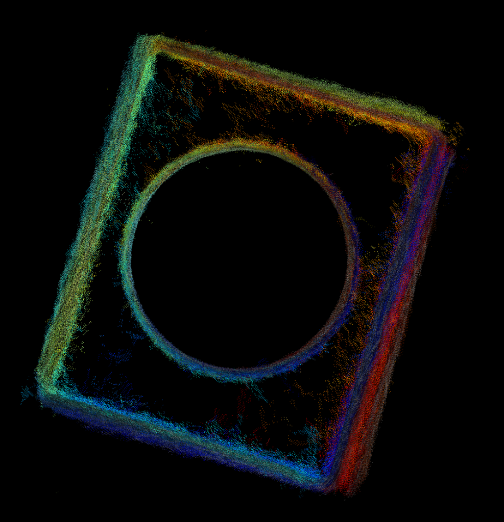
I used Ceres Solver to solve the pose graph. The results are shown below.
All the box edges line up, yay!
Method #4 – Sequential ICP with loop closure detection
Let’s revisit sequential ICP and see if we can add some pose graph optimization on top. Turns out Open3D has a built in pose graph optimizer with some sample code! Here’s what we get.
Better then vanilla sequential ICP, but not quite as good as the vision based method. Might just be my choice in parameters.
More improvements?
We’ve seen how adding loop closure to the optimization made a significant improvement in the registration accuracy. We can take this idea further and perform ALL possible matches between the captures. This can get pretty expensive as it scales quadratically with the number of images, but do-able. In theory, this should improve the registration further. But in practice you have to be very careful. The more cost functions/constraints we add the higher the chance of introducing an outlier (bad matches) into the optimization. Outliers are not handled by the simple least square loss function and can mess things up! One way to handle outliers is to use a different loss function that is more robust (eg. Huber or Tukey).
You can take the optimization further and optimize for the tracked 3D points and camera intrinsics as well. This is basically bundle adjustment found in the structure from motion and photogrammetry literature. But even with perfect pose your point cloud is still limited by the accuracy of the depth map.
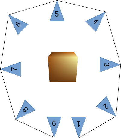
Summary of matching strategies
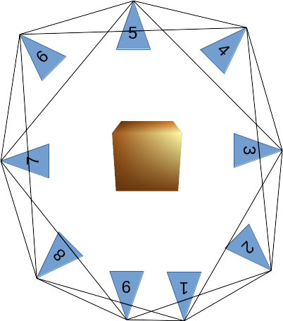
Here’s a graphical summary of the matching strategies mentioned so far. The camera poses are represented by the blue triangles and the object of interest is represented by the cube. The lines connecting the camera poses represents a valid match.
Sequential matching
Fast and simple but prone to drift the longer the sequence. Matching from capture to capture is pretty reliable if the motion is small between them. The vision based should be more reliable than ICP in practise as it doesn’t suffer from geometric ambiguities. The downside is the object needs to be fairly textured.
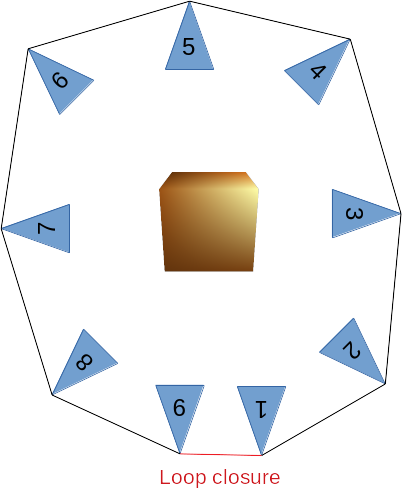
Vision based sequential matching with loop closure detection
An extension of sequential matching by explicitly detecting where the last capture loops back with an earlier capture. Effectively eliminates drift. It involves setting up a non-linear optimization problem. This can be expensive if you have a lot of parameters to optimize (lots of matched features). The loop closure detection strategy can be simple if you know how your data is collected. Just test the last capture with a handful of the earlier capture (like 10), and see which one has the most features matched. If your loop closure detection is incorrect (wrong matching pair of capture) then the optimization will fail to converge to the correct solution.
Finding all matches
This is a brute force method that works even if the captures are not ordered in any particular way. It’s the most expensive to perform out of the three matching strategies but can potentially produce the best result. Care must be taken to eliminate outliers. Although this applies to all method, it is more so here because there’s a greater chance of introducing them into the optimization.
Alternative approaches from Open3D
Open3D has a color based ICP algorithm (http://www.open3d.org/docs/release/tutorial/Advanced/colored_pointcloud_registration.html) that I have yet to try out but looks interesting.
There’s also a 3D feature based registration method that doesn’t require an initial transform for ICP but I haven’t had much luck with it.
http://www.open3d.org/docs/release/tutorial/Advanced/global_registration.html
Meshing
Open3D also includes some meshing functions that make it easy to turn the raw point cloud to a triangulated mesh. Here’s an example using Poisson surface reconstruction. I also filter out noise by only keeping the largest mesh, that being the box and tin can. Here it is below. It even interpolated the hollow top of the tin can. This isn’t how it is in real life but it looks kinda cool!
Final thoughts
Depending on your need and requirement you should always advantage of any knowledge of how the data was collected. I’ve shown a simple scenario where the user pans around an object. This allows for some simple and robust heuristics to be implemented. But if your aiming for something more generic, where there’s little restriction on the data collecting process, then you’re going to have to write more code to handle all these cases and make sure they’re robust.
Code
OpenCV camera in Opengl
In this post I will show how to incorporate OpenCV’s camera calibration results into OpenGL for a simple augmented reality application like below. This post will assume you have some familiarity with calibrating a camera and basic knowledge of modern OpenGL.

Background
A typical OpenCV camera calibration will calibrate for the camera’s intrinsics
- focal length (fx, fy)
- center (cx, sy)
- skew (usually 0)
- distortion (number of parameters depends on distortion model)
In addition it will also return the checkerboard poses (rotation, translation), relative to the camera. With the first 3 intrinsics quantities we can create a camera matrix that projects a homogeneous 3D point to 2D image point
\[camera \times X = \begin{bmatrix}
f_x & s & c_x & 0 \\
0 & f_y & c_y & 0 \\
0 & 0 & 1 & 0 \\
0 & 0 & 0 & 1
\end{bmatrix}
\times
\begin{bmatrix}
x \\ y \\ z \\ 1
\end{bmatrix}
=
\begin{bmatrix}
x’ \\ y’ \\ z’ \\ 1
\end{bmatrix}
\]
The 2D homogenous image point can be obtained by dividing x’ and y’ by z (depth) as follows [x’/z’, y’/z’, z’, 1]. We leave z’ untouched to preserve depth information, which is important for rendering.
The checkerboard pose can be expressed as a matrix, where r is the rotation and t is the translation
\[
model =
\begin{bmatrix}
r0 & r1 & r2 & tx \\
r3 & r4 & r5 & ty \\
r6 & r7 & r8 & tz \\
0 & 0 & 0 & 1
\end{bmatrix}
\]
Combining the camera and model matrix we get a general way of projecting 3D points back to 2D. Here X can be a matrix of points.
\[ X’ = camera \times model \times X \]
The conversion to 2D image point is the same as before, divide all the x’ and y’ by their respective z’. The last step is to multiply by an OpenGL orthographic projection matrix, which maps 2D image points to normalized device coordinates (NDC). Basically, it’s a left-handed co-ordinate viewing cube that is normalized to [-1, 1] in x, y, z. I won’t go into the details regarding this matrix, but if you’re curious see http://www.songho.ca/opengl/gl_projectionmatrix.html . To generate this matrix you can use glm::ortho from the GLM library or roll out your own using this definition based on gluOrtho.
Putting it all together, here’s a simple vertex shader to demonstrate what we’ve done so far
#version 330 core
layout(location = 0) in vec3 vertexPosition;

uniform mat4 projection;
uniform mat4 camera;
uniform mat4 model;

void main()
{
    // Project to 2D
    vec4 v = camera * model * vec4(vertexPosition, 1);

    // NOTE: v.z is left untouched to maintain depth information!
    v.xy /= v.z;

    // Project to NDC
    gl_Position = projection * v;
}
When you project your 3D model onto the 2D image using this method it assumes the image has already been undistorted. So you can use OpenCV’s cv::undistort function to do this before loading the texture. Or write a shader to undistort the images, I have not look into this.
Code
https://github.com/nghiaho12/OpenCV_camera_in_OpenGL
If you have any questions leave a comment.
SFM with OpenCV + GTSAM + PMVS
With some more free time lately I’ve decided to get back into some structure from motion (SFM). In this post I show a simple SFM pipeline using a mix of OpenCV, GTSAM and PMVS to create accurate and dense 3D point clouds.
This code only serves as an example. There is minimal error checking and will probably bomb out on large datasets!
Code
https://github.com/nghiaho12/SFM_example
You will need to edit src/main.cpp to point to your dataset or you test with my desk dataset.
http://nghiaho.com/uploads/desk.zip
Introduction
There are four main steps in the SFM pipeline code that I will briefly cover
If your code editor supports code folding you can turn it on and see each step locally scoped around curly braces in src/main.cpp.
To simplify the code I assume the images are taken sequentially, that is each subsequent image is physically close and from the same camera with fixed zoom.
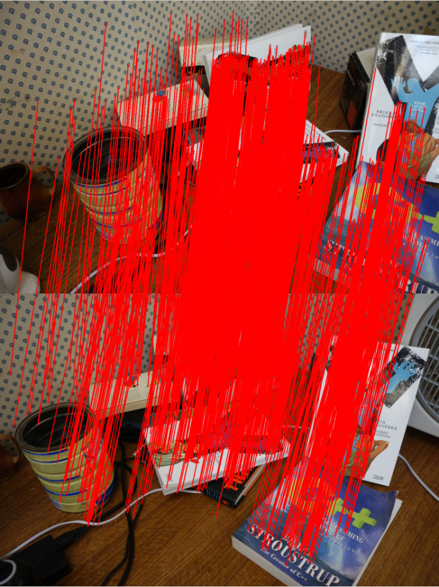
Feature matching
The first step is to find matching features between the images. There are many OpenCV tutorial on feature matching out there so I won’t go into too much detail.
There are a few ways to go about picking pair of images to match. In my code I match every image to each other. So if there N images, there are N*(N-1)/2 image pairs to match. This of course can get pretty slow since it scales quadratically with the number of images.
I initially tried ORB but found AKAZE to produce more matches. Matches have to past a ratio test (best match vs second best match) and the fundamental matrix constraint to be kept.
The only slightly tedious part is the book keeping of matched features. You need to keep track of features that match across many images. For example, a feature in image 0 may have a match in image 1 and image2. This is important because features that are seen in at least 3 views allow us to recover relative scale between motion.
Motion recovery and triangulation
This is the core part of the SFM pipeline and I take advantage of the following OpenCV functions
- cv::findEssentialMat
- cv::recoverPose
- cv::triangulatePoints
cv::findEssentialMat uses the 5-point algorithm to calculate the essential matrix from the matched features. It’s the de-facto algorithm for finding the essential matrix and is superior to the 8-point algorithm when used in conjunction with RANSAC to filter out outliers. But it is not easy to code up from scratch compared to the 8-point.
The pose from the essential matrix is recovered by cv::recoverPose. It returns a 3×3 rotation (R) and translation vector (t). The pose at camera n is calculated as follows
![T_n = T_{n-1}\left[\begin{array}{ccc|c} & & \\ & R & & t\\ & & \\ 0 & 0 & 0 & 1 \end{array}\right]](https://s0.wp.com/latex.php?latex=T_n+%3D+T_%7Bn-1%7D%5Cleft%5B%5Cbegin%7Barray%7D%7Bccc%7Cc%7D+%26+%26+%5C%5C+%26+R+%26+%26+t%5C%5C+%26+%26+%5C%5C+0+%26+0+%26+0+%26+1+%5Cend%7Barray%7D%5Cright%5D&bg=ffffff&fg=000000&s=0 "T_n = T_{n-1}\left[\begin{array}{ccc|c} & & \\ & R & & t\\ & & \\ 0 & 0 & 0 & 1 \end{array}\right]")
 is a 4×4 matrix.
Given two poses the 2D image points can then be triangulated using cv::triangulatePoints. This function expects two projection matrices (3×4) as input. To make a projection matrix from the pose you also need the camera matrix K (3×3). Let’s say we break up the pose matrix 

![T_n = \left[\begin{array}{ccc|c} & & \\ & R_n & & t_n\\ & & \\ 0 & 0 & 0 & 1 \end{array}\right]](https://s0.wp.com/latex.php?latex=T_n+%3D+%5Cleft%5B%5Cbegin%7Barray%7D%7Bccc%7Cc%7D+%26+%26+%5C%5C+%26+R_n+%26+%26+t_n%5C%5C+%26+%26+%5C%5C+0+%26+0+%26+0+%26+1+%5Cend%7Barray%7D%5Cright%5D&bg=ffffff&fg=000000&s=0 "T_n = \left[\begin{array}{ccc|c} & & \\ & R_n & & t_n\\ & & \\ 0 & 0 & 0 & 1 \end{array}\right]")
The 3×4 projection matrix for the camera n is
![P_n = K\left[\begin{array}{c|c} R_n^T & -R_n^{T}t_n\end{array}\right]](https://s0.wp.com/latex.php?latex=P_n+%3D+K%5Cleft%5B%5Cbegin%7Barray%7D%7Bc%7Cc%7D+R_n%5ET+%26+-R_n%5E%7BT%7Dt_n%5Cend%7Barray%7D%5Cright%5D&bg=ffffff&fg=000000&s=0 "P_n = K\left[\begin{array}{c|c} R_n^T & -R_n^{T}t_n\end{array}\right]")
This process is performed sequentially eg. image 0 to image 1, image 1 to image 2.
There is an ambiguity in the scale recovered from the essential matrix (hence only 5 degrees of freedom). We don’t know the length of the translation between each image, just the direction. But that’s okay, we can use the first image pair (image 0 and image 1) and use that as the reference for relative scale. An illustration of how this is done is shown below. Click on the image to zoom in.
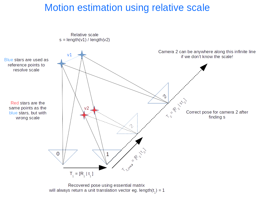
The following calculations occurs
- Recover motion between image 0 and 1 and triangulate to get the blue points. These points will be used as the reference to figure out the relative scale.
- Recover motion between image 1 and image 2 and triangulate to get the red points. Using our 2D feature matching done earlier we find that they are the same as the blue points. The rotation (
) is correct, but the translation (
) needs to be scaled.
- Find the relative scale by picking a pair of blue points and the matching red points and calculate the ratio of the vector lengths.
- Apply the scale to
Everything I’ve outlined so far is the basically visual odometry. This method only works if the images are taken sequentially apart.
Bundle adjustment
Everything we’ve done so far more or less works but is not optimal, in the statistical sense. We have not taken advantage of constraints imposed by features matched across multiple views nor have we considered uncertainty in the measurement (the statistical part). As a result, the poses and 3D points recovered won’t be as accurate as they can be. That’s where bundle adjustment comes in. It treats the problem as one big non-linear optimization. The variables to be optimized can include all the poses, all the 3D points and the camera matrix. This isn’t trivial to code up from scratch but fortunately there are a handful of libraries out there designed for this task. I chose GTSAM because I was learning it for another application. They had an example of using GTSAM for SFM in the example directory, which I based my code off.
Output for PMVS
After performing bundle adjustment we have a good estimate of the poses and 3D points. However the point cloud generally isn’t dense. To get a denser point cloud we can use PMVS. PMVS only requires the 3×4 projection matrix for each image as input. It will generate its own features for triangulation. The projection matrix can be derived from the poses optimized by GTSAM.
Example
Here’s a dataset of my desk you can use to verify everything is working correctly.
http://nghiaho.com/uploads/desk.zip
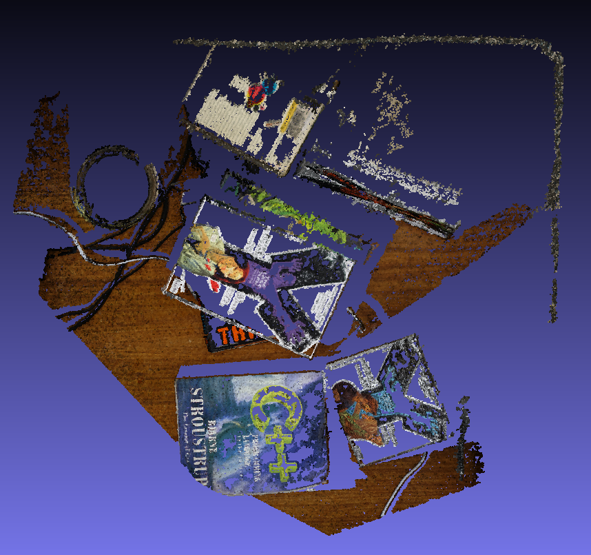
Here’s a screenshot of the output point cloud in Meshlab.
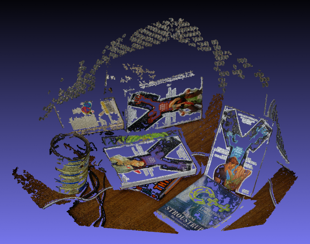
If you set Meshlab to display in orthographic mode you can see the walls make a right angle.
References
http://rpg.ifi.uzh.ch/visual_odometry_tutorial.html
EKF SLAM with known data association
In the previous post I wrote a C++ implementation of the EKF localization algorithm from the Probabilistic Robotics book. As a continuation I also wrote an implementation for the EKF SLAM with known data association algorithm. This is similar to EKF localization except we’re also estimating the landmarks position and uncertainty. The code can be found here.
https://github.com/nghiaho12/EKF_SLAM
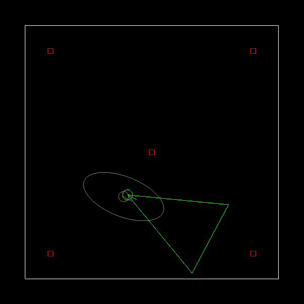
Here’s a screenshot of it in action.
EKF localization with known correspondences
Been a while since I posted anything. I recently found some free time and decided to dust off the Probabilistic Robotics book by Thrun et. al. There are a lot of topics in the book that I didn’t learn formally back during school.
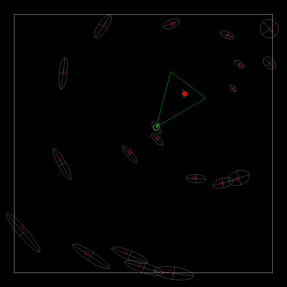
I’ve used the vanilla Kalman Filter for a few projects in the past but not the extended Kalman Filter. I decided to implement the Extended Kalman Filter localization with known correspondences algorithm. The simulation consists of a robot with a range sensor that can detect known landmarks in the world. You move the robot around using the arrow keys. The simulation is written in C++ and uses SDL and OpenGL. Below shows a screenshot. The true pose is in green, gray the EKF estimate and 95% confidence ellipse, red are the landmarks.
One addition I made was handle the case when angular velocity is zero. The original algorithm presented in the book would result in a divide by zero. You can grab and play with the code here.
An interesting behavior that I’ve been trying to understand is the EKF covariance can shrink (reduce uncertainty), even if you are only doing predictions (no correction using landmark). It’s either a coding bug or some side effect of linearization. Either way, it’s driving me nuts!
https://github.com/nghiaho12/EKF_localization_known_correspondences
Using TensorFlow/Keras with CSV files
I’ve recently started learning TensorFlow in the hope of speeding up my existing machine learning tasks by taking advantage of the GPU. At first glance the documentation looks decent but the more I read the more I found myself scratching my head on how to do even the most basic task. All I wanted to do was load in a CSV file and run it through a simple neural network. When I was downloading the necessary CUDA libraries from NVIDIA I noticed they listed a handful of machine learning framework that were supported. One of them was Keras, which happens to build on top of TensorFlow. After some hard battles with installing CUDA, TensorFlow and Keras on my Ubuntu 16.04 box and a few hours of Stackoverflow reading I finally got it working with the following python code.
from keras.models import Sequential
from keras.layers import Dense, Activation

import numpy as np
import os.path

if not os.path.isfile("data/pos.npy"):
    pos = np.loadtxt('data/pos.csv', delimiter=',', dtype=np.float32)
    np.save('data/pos.npy', pos);
else:
    pos = np.load('data/pos.npy')

if not os.path.isfile("data/neg.npy"):
    neg = np.loadtxt('data/neg.csv', delimiter=',', dtype=np.float32)
    np.save('data/neg.npy', neg);
else:
    neg = np.load('data/neg.npy')

pos_labels = np.ones((pos.shape[0], 1), dtype=int);
neg_labels = np.zeros((neg.shape[0], 1), dtype=int);

print "positive samples: ", pos.shape[0]
print "negative samples: ", neg.shape[0]

HIDDEN_LAYERS = 4

model = Sequential()

model.add(Dense(output_dim=HIDDEN_LAYERS, input_dim=pos.shape[1]))
model.add(Activation("relu"))
model.add(Dense(output_dim=1))
model.add(Activation("sigmoid"))

model.compile(optimizer='rmsprop', loss='binary_crossentropy', metrics=['accuracy'])
model.fit(np.vstack((pos, neg)), np.vstack((pos_labels, neg_labels)), nb_epoch=10, batch_size=128)

# true positive rate
tp = np.sum(model.predict_classes(pos))
tp_rate = float(tp)/pos.shape[0]

# false positive rate
fp = np.sum(model.predict_classes(neg))
fp_rate = float(fp)/neg.shape[0]

print ""
print ""

print "tp rate: ", tp_rate
print "fp rate: ", fp_rate
I happened to have my positive and negative samples in separate CSV files. The CSV files are converted to native Numpy binary for subsequent loading because it is much faster than parsing CSV. There’s probably some memory wastage going on with the np.vstack that could be improved on.
Understanding OpenCV cv::estimateRigidTransform
OpenCV’s estimateRigidTransform is a pretty neat function with many uses. The function definition is
Mat estimateRigidTransform(InputArray src, InputArray dst, bool fullAffine)
The third parameter, fullAffine, is quite interesting. It allows the user to choose between a full affine transform, which has 6 degrees of freedom (rotation, translation, scaling, shearing) or a partial affine (rotation, translation, uniform scaling), which has 4 degrees of freedom. I’ve only ever used the full affine in the past but the second option comes in handy when you don’t need/want the extra degrees of freedom.
Anyone who has ever dug deep into OpenCV’s code to figure out how an algorithm works may notice the following:
- Code documentation for the algorithms is pretty much non-existent.
- The algorithm was probably written by some soviet Russian theoretical physicists who thought it was good coding practice to write cryptic code that only a maths major can understand.
The above applies to the cv::estimateRigidTransform to some degree. That function ends up calling static cv::getRTMatrix() in lkpyramid.cpp (what the heck?), where the maths is done.
In this post I’ll look at the maths behind the function and hopefully shed some light on how it works.
Full 2D affine transform
The general 2D affine transform has 6 degree of freedoms of the form:
\[ A = \begin{bmatrix}
a & b & c \\
d & e & f
\end{bmatrix} \]
This transform combines rotation, scaling, shearing, translation and reflection in some cases.
Solving for A requires a minimum of 3 pairing points (that aren’t degenerate!). This is straight forward to do. Let’s denote the input point to be X= [x y 1]^t and the output to be Y = [x’ y’ 1]^t, giving:
\[ AX = Y \]
\[ \begin{bmatrix} a & b & c \\ d & e & f \end{bmatrix} \begin{bmatrix} x \\ y \\ 1\end{bmatrix} = \begin{bmatrix} x’ \\ y’ \\ 1\end{bmatrix} \]
Expanding this gives
\[ \begin{matrix} {ax + by + c = x’} \\ {dx + ey + f = y’}\end{matrix} \]
We can re-write this as a typical Ax = b problem and solve for x. We’ll also need to introduce 2 extra pair of points to be able to solve for x.
\[ \begin{bmatrix} x_1 & y_1 & 1 & 0 & 0 & 0 \\ 0 & 0 & 0 &x_1 & y_1 & 1 \\ x_2 & y_2 & 1 & 0 & 0 & 0 \\ 0 & 0 & 0 &x_2 & y_2 & 1 \\ x_3 & y_3 & 1 & 0 & 0 & 0 \\ 0 & 0 & 0 &x_3 & y_3 & 1\end{bmatrix} \begin{bmatrix} a \\ b \\ c \\ d \\ e \\ f \end{bmatrix} = \begin{bmatrix} x’_1 \\ y’_1 \\ x’_2 \\ y’_2 \\ x’_3 \\ y’_3 \end{bmatrix} \]
Now plug in your favourite linear solver to solve for [a, b, c, d, e, f]. If you have a 3 or more points, a simple least square solution can be obtained by doing a pseudo-inverse:
\[ \begin{matrix} Ax & = & b \\ A{^T}Ax & = & A^{T}b \\x & =& (A{^T}A)^{-1}A{^T}b \end{matrix} \]
Partial 2D affine transform
The partial affine transform mentioned early has a reduced degree of freedom of 4 by excluding shearing leaving only rotation, uniform scaling and translation. How do we do this? We start with the matrices for the transforms we are interested in.
\[ R (rotation) = \begin{bmatrix} \cos(\theta) & -\sin(\theta) \\ \sin(\theta) & \cos(\theta)\end{bmatrix} \]
\[ S(scaling) = \begin{bmatrix} s & 0 \\ 0 & s \end{bmatrix} \]
\[ t (translation) = \begin{bmatrix} tx \\ ty \end{bmatrix} \]
Our partial affine transform is
\[ A = \begin{bmatrix}RS | t\end{bmatrix} \]
Expanding gives
\[ A = \begin{bmatrix} \cos(\theta)s & -\sin(\theta)s & tx \\ \sin(\theta)s & \cos(\theta)s & ty\end{bmatrix} \]
We can rewrite this matrix by defining
\[ a = \cos(\theta)s \]
\[ b = \sin(\theta)s \]
\[ c = tx \]
\[ d = ty \]
\[ A = \begin{bmatrix} a & -b & c \\ b & a & d\end{bmatrix} \]
Solving for [a, b, c, d]
\[ A X = Y \]
\[ \begin{bmatrix} a & -b & c \\ b & a & d \end{bmatrix} \begin{bmatrix} x \\ y \\ 1\end{bmatrix} = \begin{bmatrix} x’ \\ y’ \end{bmatrix} \]
\[ \begin{matrix} {ax- by + c = x’} \\ {bx + ay + d = y’}\end{matrix} \]
Solving for [a, b, c, d]
\[ \begin{bmatrix} x_1 & -y_1 & 1 & 0 \\ y_1 & x_1 & 0 & 1 \\ x_2 & -y_2 & 1 & 0 \\ y_2 & x_2 & 0 & 1 \end{bmatrix} \begin{bmatrix} a \\ b \\ c \\ d \end{bmatrix} = \begin{bmatrix} x’_1 \\ y’_1 \\ x’_2 \\ y’_2 \end{bmatrix} \]
Notice for the partial affine transform we only need 2 pair of points instead of 3.
Final remark
Well, that’s it folks. Hopefully that gives you a better understanding of the 2D affine transform. So when should you use one or the other? I tend to the use the partial affine when I don’t want to overfit because the data has some physical constraint. On the plus side, it’s a bit faster since there are less parameters to solve for. Let me know which one you use for your application! Best answer gets a free copy of OpenCV 3.x 🙂