Last Updated on March 31, 2015 by nghiaho12
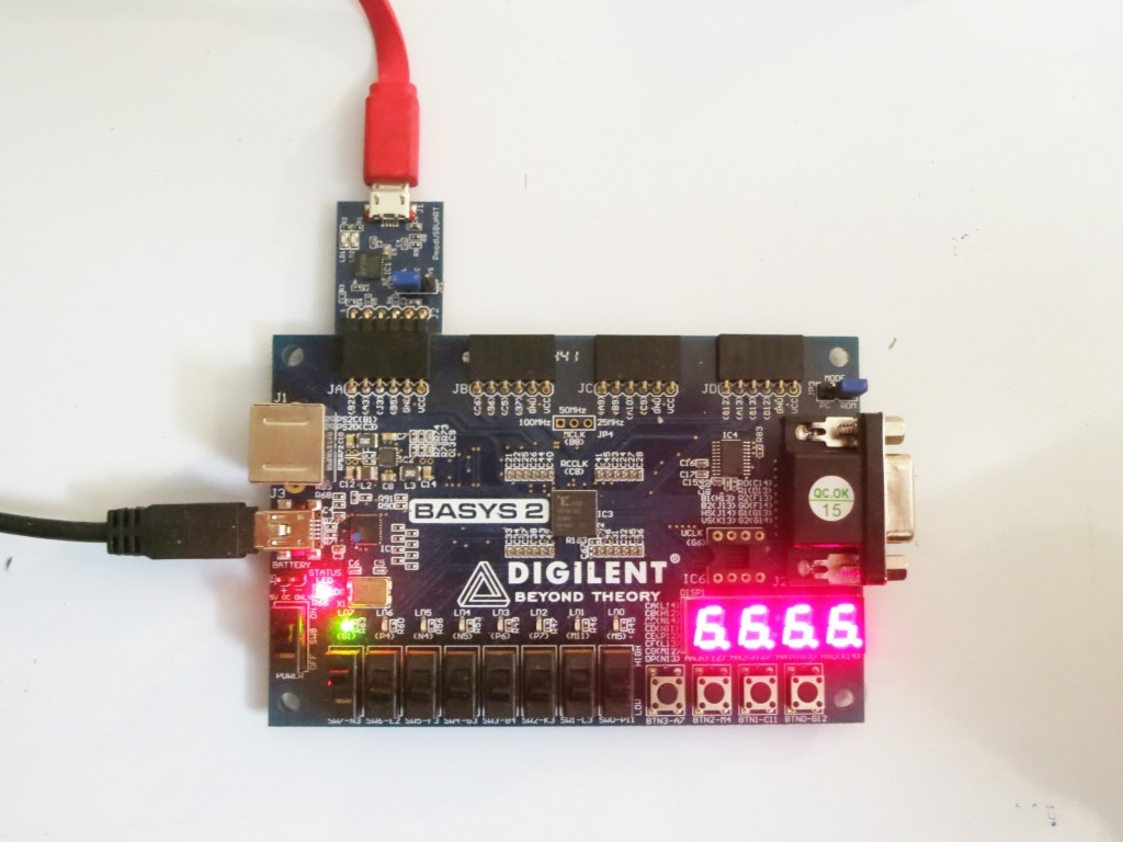
Been a while since I last posted anything. I’ve been pretty busy at my new job but managed to find some spare time to learn about FPGA. I wanted to see what all the rage is about. I purchased a Digilent Basys2 not too long ago to play with. It’s an entry board under $100, perfect for a noob like myself. Below is the Basys2 board. I bought a serial module so I can communicate using the latop, shown in the top left connected to the red USB cable.
For the first two weeks I went through the digital design book on Digilent’s site to brush up on stuff I should have remembered during my undergrad but didn’t. It’s a pretty good book for a quick intro to the basic building blocks with example code in Verilog/VHDL. I chose the Verilog book over VHDL because I found it easier to read, and less typing.
I then spent the next two or three weeks or so implementing a simple RS232 receiver/transmitter, with help from here. Boy, was that a frustrating project, but I felt I learnt a lot from that experience. That small project helped me learned about RS232 protocol, Verilog, Xilinx ISE and iSim.
Overall, I’m enjoying FPGA land so far despite how difficult it can be. There’s something about being intimately closer to the hardware that I find appealing.
My original intention for learning the FPGA is for image processing and computer vision tasks. The Basys2 doesn’t have a direct interface for a camera so for now I’ll stick to using the serial port to send images as proof of concept. Maybe I’ll upgrade to a board with a camera interface down the track.
I recently wrote a simple 3×3 filter Verilog module to start of with. It’s a discrete 3×3 Laplacian filter.
module filter3x3(
input wire clk,
input wire [7:0] in0,
input wire [7:0] in1,
input wire [7:0] in2,
input wire [7:0] in3,
input wire [7:0] in4,
input wire [7:0] in5,
input wire [7:0] in6,
input wire [7:0] in7,
input wire [7:0] in8,
output reg signed [15:0] q
    );

always @ (posedge clk)
begin
    q <= in0 + in1 + in2 +
          in3 - in4*8 + in5 +
          in6 + in7 + in8;
end

endmodule
This module takes as input 8 unsigned bytes and multiples with the 3×3 kernel [1 1 1; 1 -8 1; 1 1 1] and sums the output to q. It is meant to do this in one clock cycle. I’ve tested it in simulation and it checks out. Next step is to hook up to my serial port module and start filtering images. Stay tune!